Lumogram

The V2 form factor introduced a few significant visual differentiaions, and also folded in the incremental technology improvements that were previously ‘staged’ in V1 for the Lumogram platform.
Copyright 2024– Chuan Khoo
While the call for pilot testing is under way, the ‘V2’ edition (featuring the hexagonal pendant design) of the Lumogram is, at this time, NOT licensed under any Creative Commons license that the rest of this online resource is attributed to.
V2: Behind the Scenes
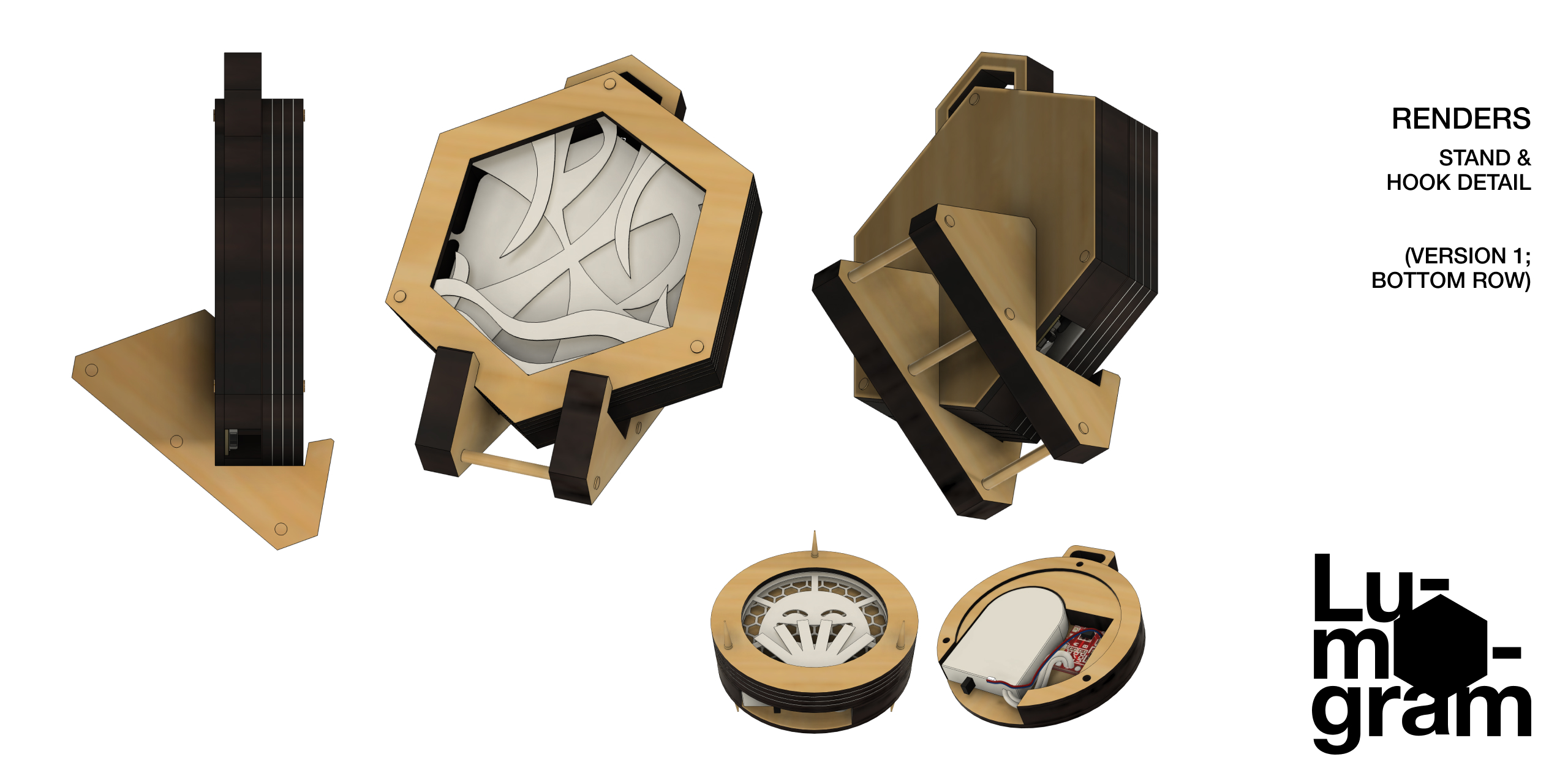
V2 Design (top row); V1 Design (bottom row)
Goals
The V2 edition of the Lumogram sought to achieve a number of goals:
- Easier assembly via a single electronics board
- Less material usage & wastage
- Minimise plastic components
- Energy-efficient lighting
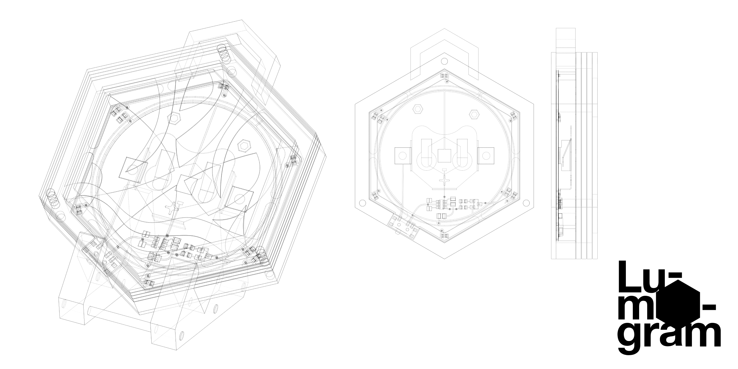
The groundwork necessary in responding to these improvements led to a careful planning of both the physical and electronic housing. Parts were modelled in 3D to produce accurate reference documents for the subsequent phases of production. The overall pendant is also now slimmer, due to the reduced height clearance of the integrated electronics.
Printed circuit board (PCB)
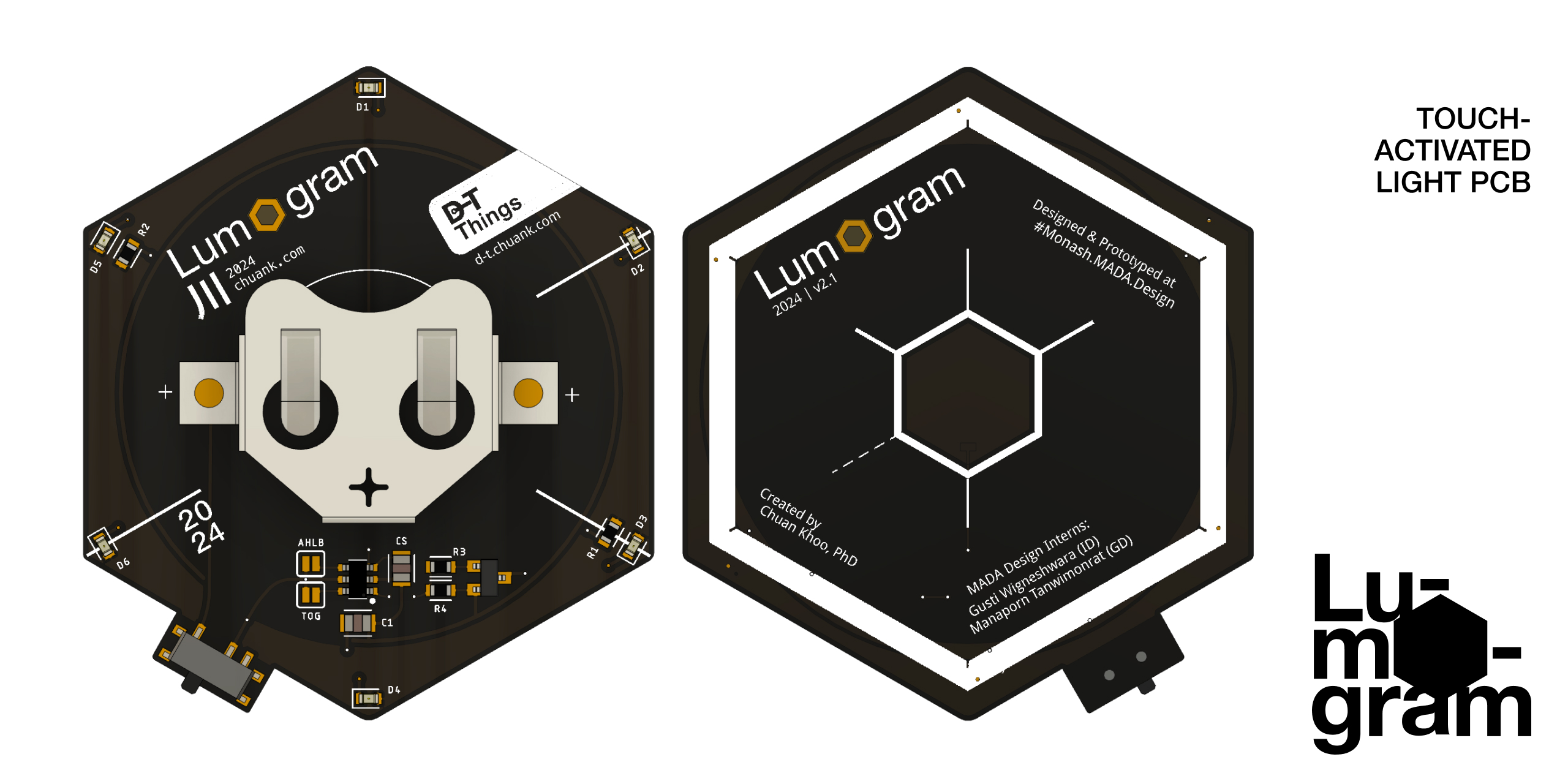
Lumogram V2.1 PCB Design
The 2-layer PCB Design utilises 6 LEDs and power control circuitry to optimise its run time and light uniformity. We can now achieve a consistent glow around the inner bezel of the Lumogram. The power switch sits comfortably and unobtrusively to one side of the device. The PCB design integrates the coin cell battery holder with the touch chip and associated discrete components, allowing this to be mass-produced at a significantly lower cost and reduced environmental impact. The specialist manufacturing facilities and their resource/energy recovery consolidates the production work with other designs, further optimising material and production processes.
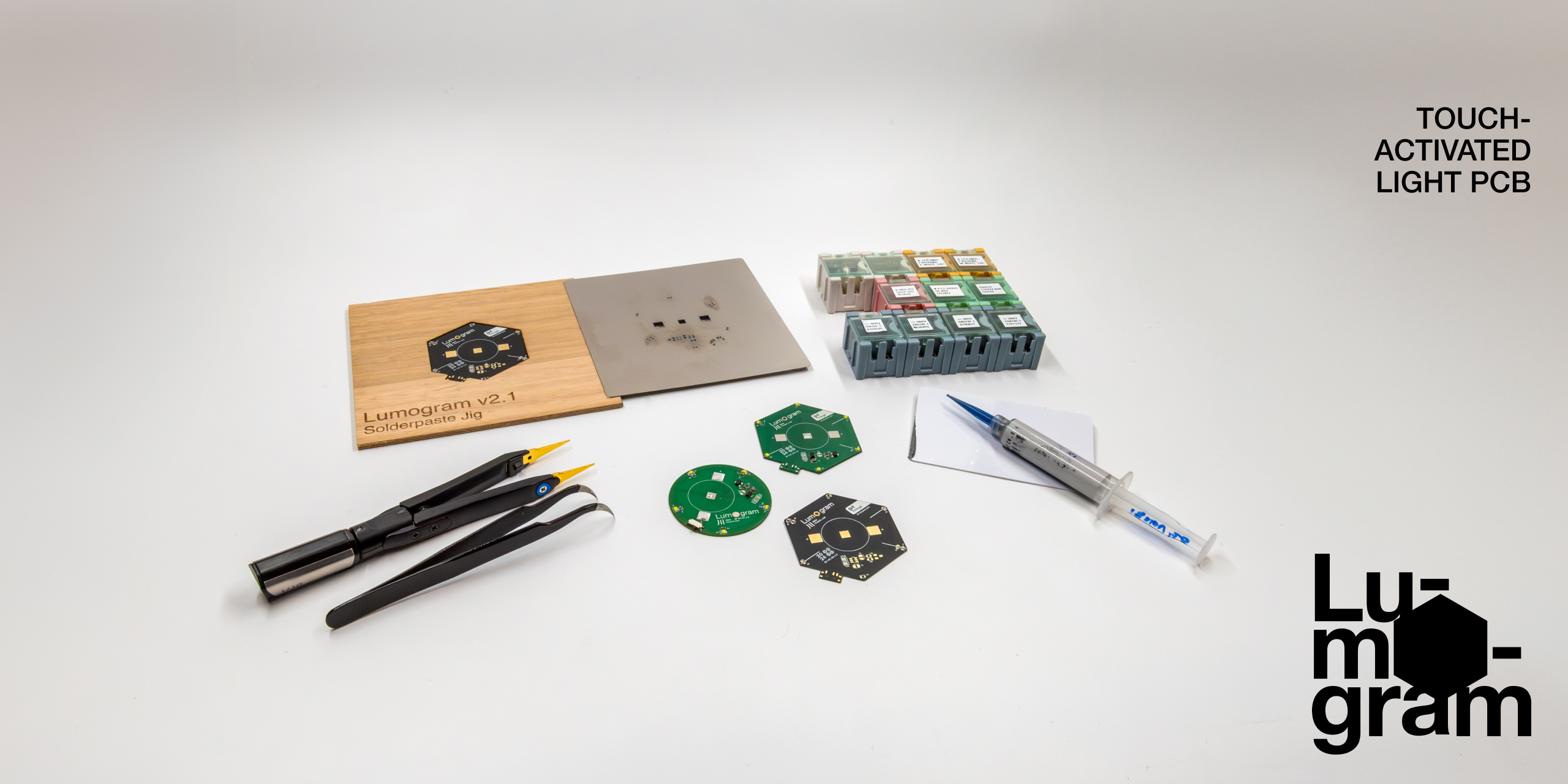
The parts and tools needed to assemble a Lumogram V2.1 PCB prototype by hand.
Designing the conditions for successful prototyping and subsequent mass production were key to Lumogram’s scalability. The SMT (surface-mount technology) used for the electronics result in a more compact layout, less plastic usage and a single, re-usable board for other touch-reactive lighting projects. The scale of the components (primarily 0805/0603) made it possible to still assemble and manufacture by hand, which provides a highly flexible production environment for creating ‘one-offs’ and test refinements. Setting up an in-house solder paste stencil jig accelerated this process.
Laser cutting
While the cartridge paper (200gsm) laser cuts were produced on a CO2-based Epilog Fusion M2 40, positive results have also been evaluated with 5W diode lasers. This includes entry-level, smaller-scale laser cutting machines for hobbyists or classrooms. As with any laser cutting equipment, please observe the necessary safety rules when operating them, and always wear appropriate eye protection.
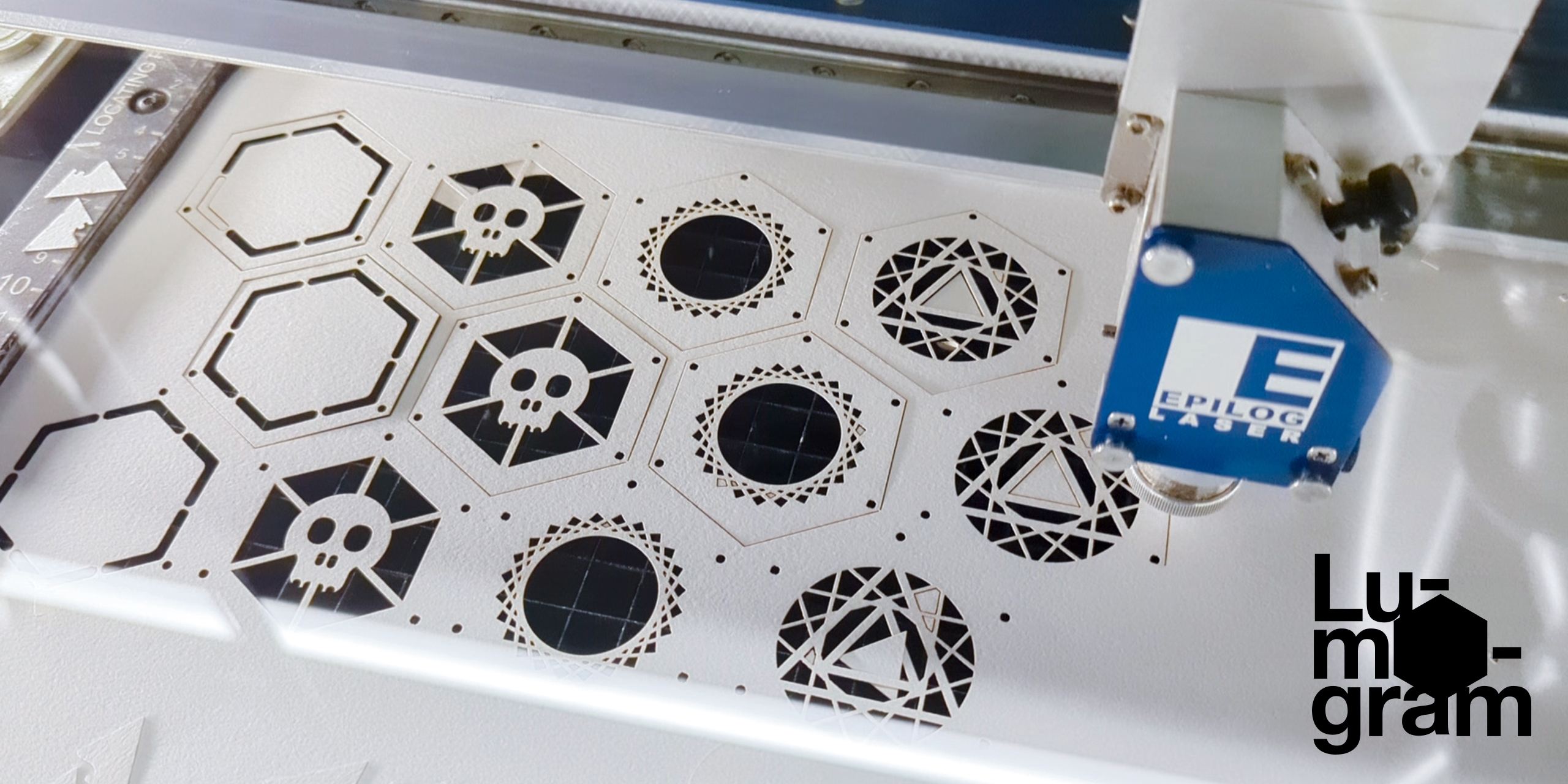
Test cut-outs being made at MADA’s dFab facility.
The usual care and considerations when laser cutting paper apply: the risk of fire, scorch marks and the strength of your exhaust fans which may send the cuts flying :)
Cri-cut or similar cutting machines have not been tested.
