Stepper Motors
Stepper motors are another option for generating rotational movement. They produce finely-stepped incremental rotations, typically 1.5° or less per step, which means if you count the number of steps to move, you can determine with reasonable accuracy just how much the output shaft has turned. Steppers can also do this in both clockwise and counterclockwise directions.
There are caveats: steppers do not have active position feedback the way servos do. We can instruct them to travel a certain number of steps, but they may over/undershoot, especially when the load on the stepper is too great, or when inertia on a large flywheel stops it from braking properly. Use steppers with this in mind. A quick solution is to implement a way to ‘reset’ the position – this is often called ‘homing’ (see below).
Learn the basics about stepper motors here. Further details are also available in my lesson slides.
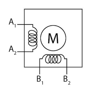
The wiring for steppers can be a bit more involved, given how a stepper motor is designed. The most common steppers you will encounter are bipolar steppers, which have two separate coils that energise in sequence, resulting in the ‘steppped’ motion of the output shaft:

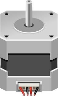
NEMA stepper motors are used in many consumer-grade 3D printers.

Simplified schematic of a 4-wire bipolar stepper – the windings are separated into 2 coils, A and B. (The actual stepper motor looks more complex as the windings are alternated around the entire motor shaft)
Using steppers mean that you will have to use a stepper motor driver of some kind. There are purpose-built stepper motors such as the EasyDriver that connects to most microcontrollers without much difficulty. Like DC motors, stepper motors cannot be directly driven by a microcontroller, as they demand quite a bit of electrical power.
Using a basic Arduino kit?
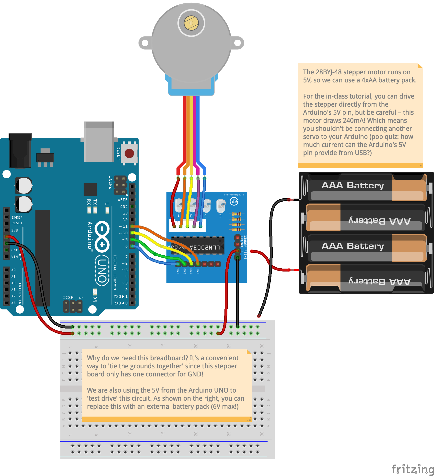
If you are learning how to work with steppers using the basic Arduino prototyping kit in your class, we are using a specific pairing of a small stepper motor and an ULN2003 Darlington transistor array as the driver. See the recipe below for wiring and code.
Where are stepper motors often used?
Many consumer-grade 3D printers utilise NEMA-standardised stepper motors, as defined by the US National Electrical Manufacturers Association. The rectangular blocks of aluminium stepper motors, such as the image above, come in different ‘heights’ and therefore different power/torque combinations.
Other uses of stepper motors include inkjet printers, vinyl cutting machines, consumer-grade CNC, air conditioning louvres, photocopiers, flatbed scanners, and in general, any situation where position awareness is required.
Stepper Motor ‘Homing’
Speaking of position awareness, adding a stepper motor into your project might not necessarily be a very straightforward task. If your project requires the stepper to ‘know’ where it’s ‘zero’ mark is, you must implement a homing routine upon powerup. Think is this as similar to how an inkjet printer or flatbed scanner starts up and whirs its head back and forth to ‘find’ the starting point.
This of often associated with belt-driven mechanisms, which will tell you what sort of homing switch is necessary. Typically, a small microswitch is all that is needed, with other options including Hall-effect switches (magnetic), or induction sensors.
The following video by Brainy Bits demonstrates this homing implementation, along with example code in the description of the video:
Stepper Motor Homing
It is almost a necessity to implement this homing sequence if you are intent on building a kinetic system that needs to keep track of its position. Think of this as how an inkjet printer starts up – that whirring and initial moving of the print head is the printer finding its ‘home position’ at startup.
For more general information on stepper motors, refer to the Curated Links page.
The wiring recipes below are split into two very different stepper motors and driver examples, for the Arduino UNO R3 and Particle Photon respectively. With some additional tweaking either set of hardware will work with either microcontroller, paying attention to the 5V / 3.3V system voltage differences between the two. Please refer to the additional notes inside each setup carefully.
AccelStepper
The examples in the above video and the recipes below utilise Mike McCauley’s AccelStepper library, a much better alternative over the ‘standard’ Stepper libraries that do not support acceleration features. Acceleration and deceleration is particular critical in mechanical engineering, especially when it comes to high loads – by allowing the stepper motor to gradually reach top and zero speeds, there is minimal ‘jerk’ in the movement, resulting in less hysteresis (i.e. unwanted oscillations) of the mechanism.
Wiring & Code
For a refresher on how to use the code in this recipe, click here.
Select a microcontroller platform in the tabs below to view the wiring and code meant for the platform:
-
Breadboard diagramIn this recipe, we are using the low-cost
28BYJ-485V stepper & the ULN2003 transistor array. This is commonly found in various Arduino learning kits and is a great little stepper originally designed to create the automatic sweeping motion in air conditioning louvres.The stepper driver board is a ULN2003 transistor array (7 Darlington transistors inside one chip) of which we are using 4 pins to control the stepper with. A great online resource for the 28BYJ-48 and ULN2003 pairing can be found here.

Stepper Motor circuit
Download Stepper Motors Fritzing file
In this example we have a non-interactive setup, where the code tells the stepper motor to traverse one revolution, before reversing for two revolutions, and repeating this clockwise-counter-clockwise rotation again. Contrast this with the Particle Photon code where a pushbutton is used – both utilise variants of the same library and the code logic can be integrated in either setup to create the same effect on the other recipe.
Libraries Used- AccelStepper
Code1 2 3 4 5 6 7 8 9 10 11 12 13 14 15 16 17 18 19 20 21 22 23 24 25
#include <AccelStepper.h> // Define a stepper using a ULN2003 transistor array = 4 pins needed! AccelStepper stepper(AccelStepper::FULL4WIRE, 8, 10, 9, 11); int pos = 2038; // 2038 steps because this 28BYJ-48 5V stepper has 2038 steps per revolution; void setup() { stepper.setMaxSpeed(1000); stepper.setAcceleration(50); stepper.setSpeed(200); stepper.moveTo(pos); } void loop() { // if at the end of travel, go to the other end if (stepper.distanceToGo() == 0) { delay(500); pos = -pos; stepper.moveTo(pos); } // tell AccelStepper to calculate and execute stepper actions stepper.run(); }
-
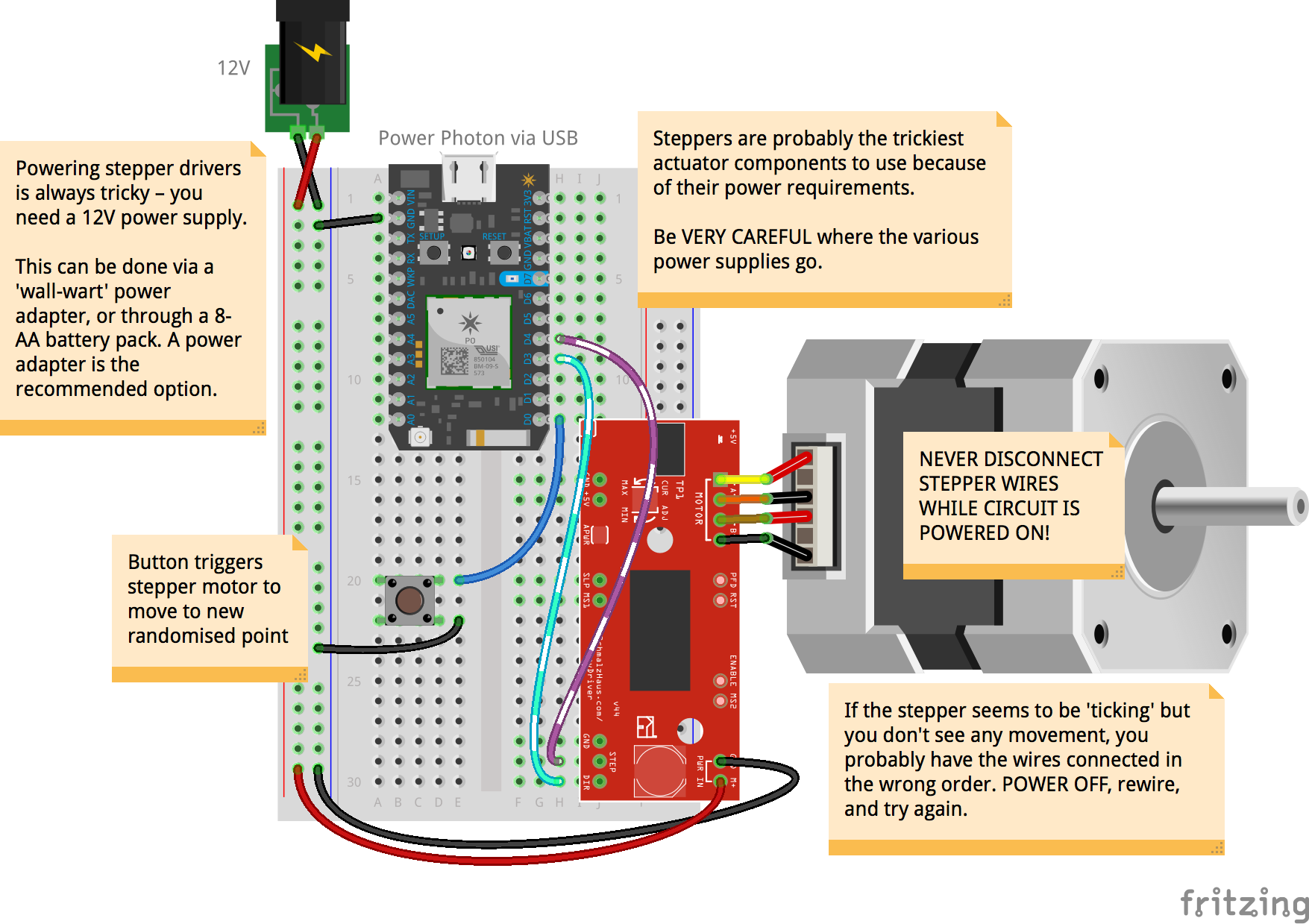
Breadboard diagramIn this recipe, designed specifically for the Particle Photon, take extra caution with the power supplies. We need 12V to power the stepper circuit – a 8xAA battery pack will do, or better yet, get a wall-wart transformer to supply the 12V from the wall outlet. You NEVER want to connect this 12V into your Photon’s VIN/3V3, you will instantly destroy your Photon.

Stepper Motor circuit
In this example, we are using a single pushbutton to trigger the stepper motor. The code is kept simple – each time the button is pushed, it calculates a randomised point that the stepper motor will travel to.
Libraries Used- ACCELSTEPPERSPARK
Code1 2 3 4 5 6 7 8 9 10 11 12 13 14 15 16 17 18 19 20 21 22 23 24 25 26 27 28 29 30 31 32 33 34 35 36 37 38 39 40 41 42 43 44 45 46 47 48 49
// This #include statement was automatically added by the Particle IDE. #include <AccelStepper.h> // how long (ms) between each sensor update? feel free to // change this value from 5 to 5000; use 10 as a start // if you are logging via Particle.publish, this must not be anything less than 1000ms! #define INTERVAL_BETWEEN_SENSE 10 // initialise the timer Timer dataUpdateTimer(INTERVAL_BETWEEN_SENSE, doDataUpdate); // Define a stepper and the pins it will use AccelStepper stepper(AccelStepper::DRIVER, D4, D3); // EasyDriver connected to D4 (step), D3 (dir) // code in this setup function runs just once, when Photon is powered up or reset void setup() { Serial.begin(115200); // Open a connection via the Serial port – useful for debugging delay(5000); // Common practice to allow board to 'settle' after connecting online pinMode(D3, OUTPUT); // goes to IN1 of DRV8871 controller pinMode(D4, OUTPUT); // goes to IN2 of DRV8871 controller // we're also connecting a pushbutton to D0 to 'trigger' a randomised stepper movement pinMode(D0, INPUT_PULLDOWN); dataUpdateTimer.start(); // start our dataUpdateTimer } // code in this loop function runs forever, until you cut power! void loop() { stepper.run(); // we need to run this in loop to 'update' the stepper's position constantly } // doDataUpdate runs every interval as set by INTERVAL_BETWEEN_SENSE void doDataUpdate() { int D0State = digitalRead(D0); // read state of button if(D0State==HIGH) { stepper.moveTo(rand() % 200); stepper.setMaxSpeed((rand() % 200) + 1); stepper.setAcceleration((rand() % 200) + 1); } // form a human-readable output for viewing via the Serial port String output = "steps to go:" + String(stepper.distanceToGo()); // prints this out the Serial port (coolterm) for us humans Serial.println(output); }
