Power to your circuits
It’s important to know how to calculate total power consumption in your circuit. This allows you to specify, with a good degree of certainty, a reliable power supply for your project’s needs.
Providing insufficient power to your circuit usually results in brownouts: power failures which will cause your circuit to operate erratically. The most common sign of insufficient power, if you’re using a microcontroller, is seeing the device power cycle itself without warning.
The other sign might be more obvious – if you’re using a ‘wall-wart’ or ‘plugpack’ AC-to-DC adapter, it’s going to get really hot before it throws itself into thermal protection mode and shut down – that’s if you’re lucky and not destroy the electronics in the adapter! Batteries get hot when you draw too much power too quickly, too, so watch out for those signs.
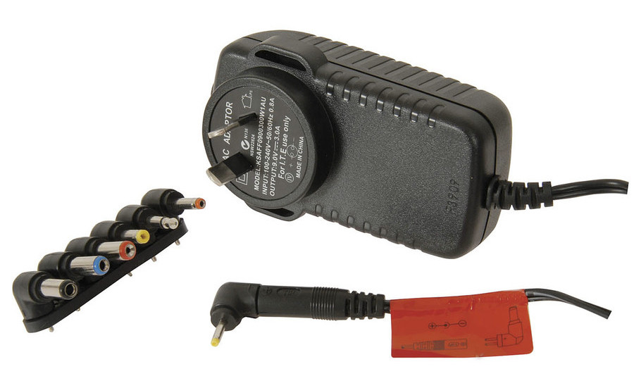
AC-to-DC adapter, sometimes known as a ‘wall-wart’ or a ‘plugpack’. Read those labels, they tell you if it’s suitable for your needs!
How to calculate power consumption
There are two ways to do this. The first way is theoretical, i.e. you calculate all of the components’ power consumption with the help of datasheets. The second way is to use a digital multimeter (DMM), set to measure amperage, or a bench power supply that gives you a readout of the power supplied to your circuit.
Other ways to measure with tools
Adafruit has the USB Voltage Meter with OLED Display that provides USB-powered circuits a quick and easy way to measure power consumption. It’s handy but only works easily if you are drawing 5V from a USB power source.
If you want absolute precision in measuring power consumption, consider Dave Jones’ (of EEVBlog fame) µCurrent GOLD.
It’s obvious that the latter method (using DMMs / bench power supplies) will give you more exact, ‘real-world’ readings, but there are limits to how much current the DMM can measure safely. The theoretical method lets you ballpark the initial expected power consumption profile for your circuit and is usually the first step to determining the right power supply rating for your needs.
To get started, you need to be familiar with the concept of voltage and amperage.
Electrical power, measured in Watts, is derived by multiplying your supply voltage with the amperage. For example:
5V x 2A = 10W
Use this formula to easily convert between ratings printed on the power supplies.
Know your voltage(s)
The assumption here is that you are working with DC voltage. Circuits powered by batteries, USB, or a ‘wall-wart’ AC-DC adapter are an example of DC circuits.
Here are some typical scenarios:
- If you are using an Arduino UNO, and using just NeoPixels, it’s very likely that you will be using 5VDC throughout the circuit.
- If you are using 12V solenoids with an Arduino UNO, then you’ll have to contend with multiple supply voltages – a 12V power source for your solenoids, as well as a 5V supply that your Arduino UNO needs. In this case, however, because the Arduino UNO has a on-board voltage regulator (that converts 6-12V to 5V), you do not actually need an additional 5V voltage regulator and therefore all you need is 12VDC.
- If you are using a Particle Photon with just sensors that run on the 3.3V pin, you need just a 5V power source. Like the Arduino UNO, the Particle Photon has a onboard voltage regulator that provides the voltage ‘conversion’ from 5V to 3.3V to power the system chip and the other sensors connected to it.
Once you know the voltage, we can look at power consumption.
RTFM: Calculating from datasheets
Go to each component’s datasheet to get a nominal rating of power consumption. It’s important to note the term nominal or typical, which points to the average power consumption rating. This might change depending on the component and how the circuit is utilised.
For example, look at the Particle Photon:
| Activity | Power consumption |
|---|---|
| WiFi transmitting | 235-430mA |
| WiFi standby | 80-100mA |
(refer to the Photon datasheet for full details)
This means if you have a project that uses WiFi very actively, you will want to lean towards the peak consumption of 235-430mA a bit more than the typical 80-100mA.
RTFM?
Notice how the datasheet is your crucial guide to all components. There’s a reason why the rather terse acronym RTFM exists…
Once you have the mA ratings found, add them all up. For example, using a Photon that sends WiFi data every 10 minutes, but uses say a sensor that consumes 40mA typical, will give us about:
100 + 40mA = 140mA
With this value, it is good practice to add a 20% buffer to compensate for inefficiencies, power fluctuations and peak draw:
140mA + 20% = 168mA
You now have the total theoretical power consumption for your circuit!
I’ve got the power, now what?
With the voltage and amperage known, you can now look around for a suitable power supply.
AC-DC adapters: wall outlet power source
We’ll focus on ‘plugpack’, ‘wall-wart’ power supplies first. The image at the top of this page shows an example.
It’s likely no manufacturer will have one that is exactly what you need, so find a power supply with the correct voltage, and select the next step upwards from your amperage. In our example above, you’ll be hard-pressed to find a 168mA plugpack, and the next closest one might be 500mA, so choose that.
More amps in a plugpack is fine; this means it just has more power to spare. A circuit will only draw as much current as it needs, so you won’t consume more power.
Read the one shown on this page: the OUTPUT label describes a 5V/3A supply.
Warning
You need to make sure the voltage is the same though!
Another important detail for plugpacks is the barrel jack connector. There is a polarity that you have to follow.
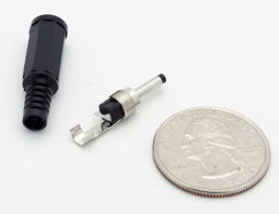
A DC barrel jack, disassembled
Power barrel jacks have polarity! If you are going to solder your own jack to your power supply, be careful that you use proper wire colours to help you identify the polarity of the power supply!

Positive Tip Polarity

Negative Tip Polarity
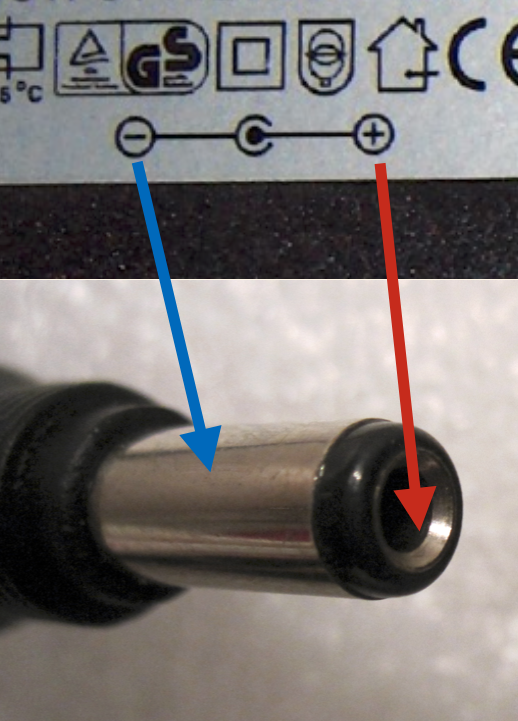
Polarity is always printed on a power supply. In this case we have a positive tip polarity.
Most devices have positive on the inside ‘tip’, as shown in diagram A.
Use these labels which can be found printed on AC/DC adapters as a reference, and solder your own jacks carefully!
Batteries
The other alternative of course is batteries. Let’s be more environmentally-aware and use rechargeable batteries instead of the alkaline ones.
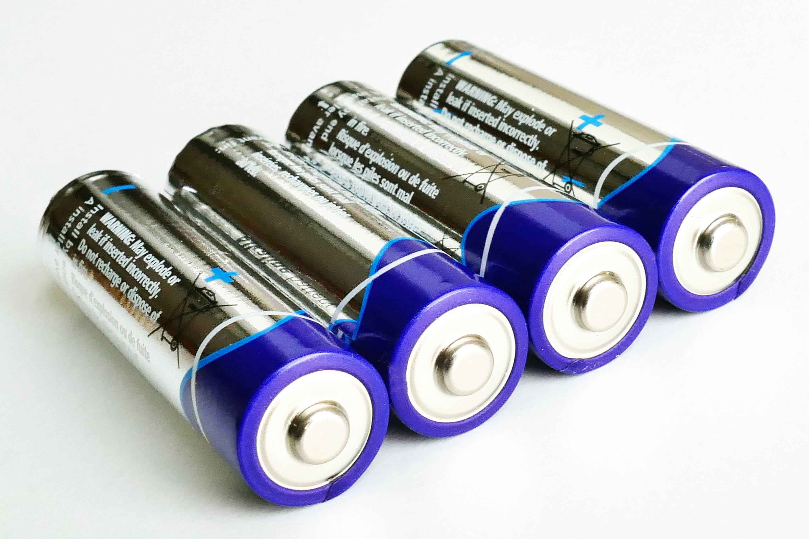
A good start is the 4xAA battery holders you can get from an electronics supply store. 4xAA = 4x1.5V = 6V. However, rechargeable NiMH batteries are rated at 1.2V, so that will give you 4.8V, which is usually still sufficient for 5V systems (but might not last long).
The challenge of such AA / AAA / C / D size batteries is that they have a fixed voltage, which usually implies that you need some form of a voltage regulator to get them operating at your ideal voltage. For example, 2xAA will give you between 2.4 and 3V, not quite sufficient for a 3.3V system. Likewise, a 4xAA gives 4.8-6V, not exactly a very strong voltage to power a 5V Arduino UNO on the low end, and a touch too high at 6V. In such cases you will need to rely on voltage regulators, a topic that deserves a separate section (see next). Meanwhile come speak to me if you have questions, or access the internet for tutorials on voltage regulators.
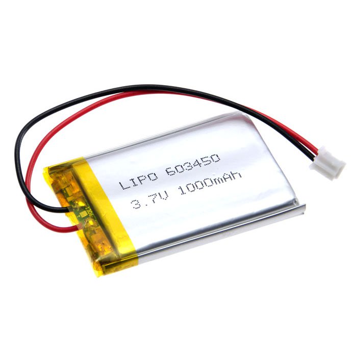
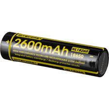
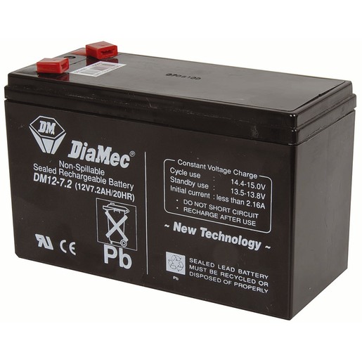
In summary, for battery technologies, you typically have:
| ‘standard’ Alkaline / NiMH (AA/AAA/C/D) | Lithium Polymer | Lithium Ion | Sealed lead acid (SLA) | |
|---|---|---|---|---|
 |
 |
 |
 |
|
| NOMINAL VOLTAGE* | 1.5 per battery (alkaline), 1.2V (rechargeable NiMH) | 3.7V | 3.6V | 12V, sometimes 6V |
| CURRENT | Around 2000mAH | Typically 150mAH-2600mAH, varies depending on what you get; single-cell LiPos are easiest to work with | Typically 2200mAH-2600mAH, varies depending on what you get; single-cell Li-Ions are easiest to work with | Typically 40AH to 125AH |
| BENEFITS | Easy to source and use | Compact, lightweight, easy to embed into small enclosures | Not as compact as LiPos, but it’s similarity in volume to AA batteries (the 18650 variety) makes it a familiar form factor to design around | Plenty of charge can be had; great for projects requiring long run time on a single charge, or off-grid setups that use high-energy components |
| DISADVANTAGES | Not very environmentally-friendly | Can explode if mishandled, requires special charging circuitry | Can explode if mishandled, requires special charging circuitry | Heavy, bulky |
| EASE OF INTEGRATION | Easiest; get those battery holders, you can wire them both in series/parallel to get the desired voltage/amperage for your needs | Moderate, always take care handling them! Special charging circuitry is required for safe operation and regulation | Moderate, always take care handling them! Special charging circuitry is required for safe operation and regulation. | Difficult, size and weight is a big issue, plus charging electronics |
| ADDITIONAL NOTES | Think about the environment when using these! Or try not to use them unless absolutely necessary, and go for NiMH rechargeable ones instead (but be aware of the voltage difference) | Single-cell LiPos are easiest to deploy, use and recharge particularly if you intend to design a product where recharging the battery from say a USB cable is an unavoidable part of its use. Multi-cell LiPos require special balanced chargers to recharge | Some 18650 cells have solder tabs on its ends for permanently affixing to circuit boards, others have AA-style terminals meant to be inserted and removed easily. Some others have a built-in micro-USB charging port which can be really handy for recharging | Use deep-cycle SLAs as they are designed for full discharge; regular car batteries will die very quickly if they go anywhere below 80% charge |
* Please note that voltage levels are nominal
They represent the typical voltage when the battery is ‘healthy’. For example, LiPo batteries go up to 4.2V when fully charged, draining down to 2.8V when empty.
Lithium-polymer (LiPo) batteries
Lithium-polymer (LiPo) batteries are hazardous if not handled properly. Piercing it, over-discharging, shorting or draining too much instantaneous current from it can result in massive LiPo fires:
Voltage Regulators
Voltage regulation refers to the stabilisation of a voltage level to a desired value, in order to power a circuit. This is particularly crucial if you have a battery-based setup where the supply voltage varies over the lifespan of the battery’s charge.
Generally speaking, you always want to have a higher voltage source that you regulate downwards. For example, if you have a 5V Arduino running 8 Neopixels (that also run at 5V), a 12V power supply connected to a voltage regulator stepping it down to 5V will be an ideal scenario.
Typically, microcontrollers will have onboard voltage regulators that allow for a degree of flexibility in power sources to be provided to it. For example, the Arduino UNO R3 can take anywhere from 6-12V into its VIN pin and it will happily regulate the system voltage to 5V (and 3.3V). Some I2 sensor boards also have a voltage regulator, that steps down 5V to the sensor’s operating voltage (3.3V or 1.8V), which makes for an easier connection to a wider range of microcontrollers.
There are two core types of voltage regulation: linear and switching.
Linear voltage regulators provide a cleaner regulation.
Switching regulators, also known as buck converters, chop off excess voltage to
Summary
You can break down theoretical power calculation thusly:
- For each known operating voltage, add up power consumption (mA) ratings.
- Add a 20% overhead to compensate for power supply inconsistencies and headroom. For example, a circuit requiring 5V/1.6A means you should look for a 5V/2A power supply.
- Source for a power supply that can provide that particular power at the right voltage. If you can’t find exactly the rating you need, always remember that you can always get a power supply that has a higher AMP rating, but the same VOLTAGE. A circuit will only require as much current as it needs.
- More complicated multi-voltage setups will require you to source for either multi-output power supplies, or separate ones. This just means you repeat the process for each voltage level.
