
Building Circuits
This page talks about the basic do's and don'ts of building electronic prototypes; of lessons and little discoveries I've made over time. I won't go into the details of designing your own PCB and surface-mounted technology (SMT) here; there are other technical resources on the Internet that offer suitable introductions.
The basic points covered in this article is meant develop an understanding of the nature of electronics in the real world, and how these details often boil down towards making smart decisions in your circuitry to make it more resilient.
Most of the techniques discussed here can be easily extended to more complex embedded projects – it's a matter of selecting purpose-built components, miniaturisation, and optimisation after you get the basic functionality going.
Briefly, this article addresses:
- Part 0: Using better setups for improved sensing
- Part 1: Know your sensors’ characteristics
- Part 2: What sensor do I use?
- Part 3: Sensor Interfaces, Wiring, Wireless
- Part 4: Signal Filtering
Part 0: Using better setups for improved sensing
When it comes to electronic prototyping, the breadboard's your best friend for its ease of use and relative simplicity. However, especially for more sensitive analog sensing circuits, the issue of RF interference, electronic noise, EMF (electro-magnetic interference), will come into play and potentially impact your readings from the sensors.
A. Stop using breadboards!
Once you have your circuit functioning and set up on a breadboard, move on to create a more compact and electrically-neater circuit using a prototyping board. This is especially important for sensitive analogue sensing. The objective of this is to create circuits with shorter traces, and as few traces as feasible. The other plus side to this a more professional-looking circuit, not a ‘rat's nest’ of cables and breadboards sticking out under your work.
Jumper wire in breadboards are also notorious for coming loose during moments you least expect them to. Due to their internal construction, breadboards may act as antennae for radio frequencies (RF) that might impact the accuracy of certain components.
Here is a table listing various ways in which you can ‘upgrade’ your breadboard circuits:
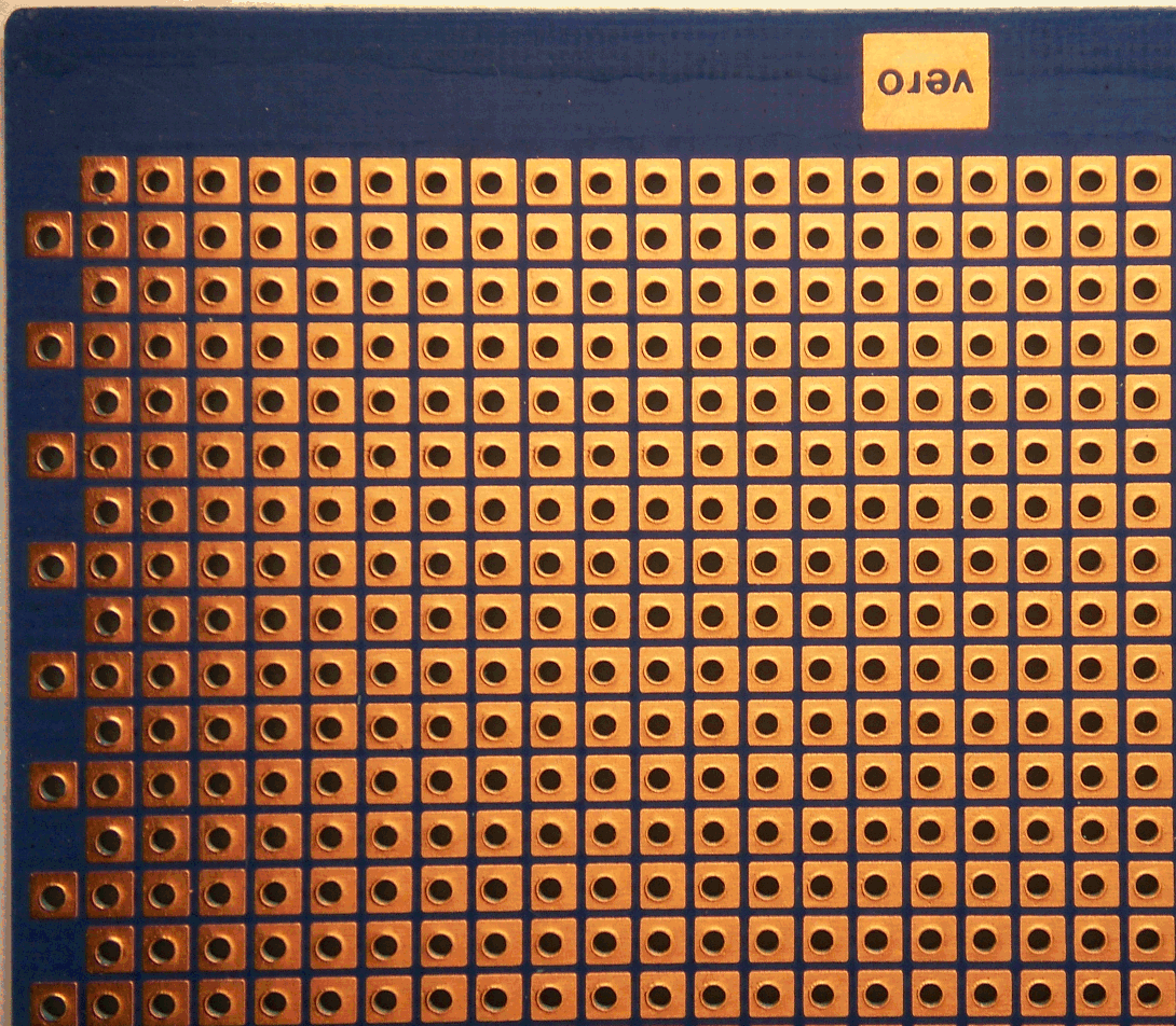
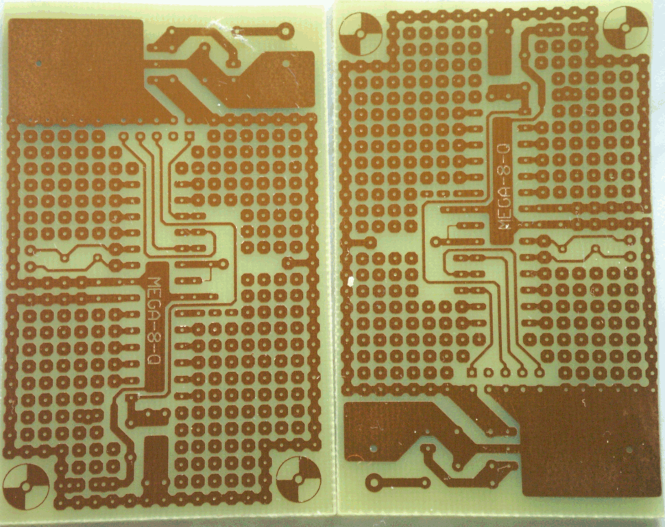
| Pre-drilled prototyping board (‘perfboard’) | Etching your own circuit board | Send to PCB fabrication house | |
|---|---|---|---|
 |
 |
 |
|
| COST | Low | Moderate-high | High (depends on size) |
| EFFORT | Low | High | Moderate-high |
| WAITING TIME | None | Time to prepare resist, etching, tinning (optional), drilling of holes | 2-4 weeks |
| SKILLS NEEDED | Soldering | Etching, drilling, soldering, PCB layout software/Illustrator | PCB layout software, adhering to design rules of PCB fab house. Favours those who already know how to use PCB software. |
| ADDITIONAL NOTES | Jumper wires still need to be soldering when necessary, watch out for shorts, or unnecessarily long wires | Probably the most time consuming, and takes a while to master the technique (the toner transfer method works very well for prototyping needs). Nevertheless, a skill worth acquiring! | Most professional finish, good if you need that polished touch when proposing your prototypes to interested parties. Biggest issue is when you get the PCB design wrong – it's a case of waiting another 2-4 weeks for corrected board to arrive. |
| LINKS | perfboards | DIY etching | PCB fab |
At the bare minimum, transfer your tested prototype circuits onto perfboard.
For a start, consider using these perma-protoboards from Adafruit. They have the same layout as breadboards, so transferring the electrical layout from breadboard to protoboard is painless, and won't require you to remap component leads and wiring – just copy the layout over and solder the components in.
B. Consider alternative Arduino form factors
Besides the relatively large Arduino UNO R3, you can use other Arduino boards that might give you more flexibility in embedding the microcontroller (and related electronics) in a smaller space. It is almost certain that you will have to build your own supporting circuitry using perfboards or etched/printed circuit boards.
Smaller-scale microcontroller boards tend to have minimum circuit protection, sometimes completely excluded. More care needs to be taken when working with these. You may also need a separate programmer for some of these boards, in order to upload sketches to them.
Here are some recommended boards to consider:
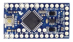
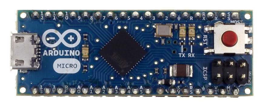
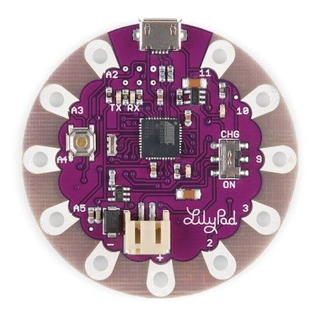
| Arduino Pro Mini | Arduino Micro | Lilypad | Ruggeduino |
|---|---|---|---|
 |
 |
 |
 |
| Tiny, comes without soldered headers so you can customise how it's mounted on your object. Requires FTDI-based programmer to upload sketches to it. | Slightly longer then the Pro Mini, built-in USB micro socket for direct programming (uses the newer ATMEGA32u4 chip). Can emulate a mouse or keyboard natively. Functionally identical to the larger Leonardo. | Excellent for wearable circuits where circuitry and sensors need to be attached flat to clothing or flexible material. (old version) Simple: Requires FTDI programmer (new version) Arduino USB: Essentially a Leonardo |
Full-sized Arduino UNO R3, but with very robust circuit protection on all I/O pins, reverse voltage protection |
| Available in both 3.3V and 5V versions, onboard regulator can be enabled/disabled, which is great for wireless, low power battery-based applications as you power the Arduino from an existing regulated 3V output (and not waste the power going into the onboard regulator) | 5V only. Great for smaller embedded setups, not exactly as battery-friendly as the Pro Mini, but still very decent. Uses USB micro plug. | 3.3V only, designed for battery-powered function. Might also work well for embedding in spherical or cylindrical setups. | 5V only. Due to the protection circuitry on the board, the Ruggeduino is very forgiving for new Arduino users, and handles unexpected voltage spikes or shorts much better than stock Arduino boards. The board of choice for semi-permanent/permanent Arduino-based installations. |
| Officially retired, but still widely available. Sparkfun version: Relatively cheap due to a thinner (0.8mm) board, easily ordered (stocks tend to fluctuate). Chinese-made variants are extremely cheap but have wildly variable quality (some boards come labelled at 5V when they are 3.3V, for example). | Somewhat expensive due to its Arduino branding. However, open-source variants are beginning to show up on the market from various sources around the world. | Can be difficult to source sometimes, due to smaller production runs. With the relatively fragile nature of these boards, it is highly recommended to get the official Lilypads from Sparkfun (or one of Sparkfun's distributors). | Expensive due to additional protection components. Ships only to US, which means you must find a 3rd party shipping service to get these boards outside of the US. Expect a long delivery. However, it's well worth the hassle for a robust Arduino, especially for electrically noisy/unstable environments. |
| Arduino Store link | Arduino Store link | LilyPad USB LilyPad Simple |
Rugged Circuits |
C. The weakest physical link – wiring
You can have the most fantastic hardware, electronics and assembly, but all it takes is to have shoddy wiring, either through cable choice or poor practice, to wreck your sensing.
Tip #1: Refer to the sensor's datasheet and add decoupling capacitors of the recommended rating, if suggested. Attach the leads of the capacitors as close as you can to the sensors.
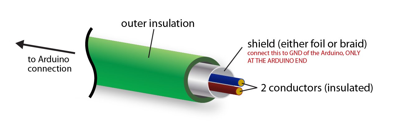
Tip #2: Use insulated cable with shielding. To use shielding correctly, connect it to the GND of just ONE end of the circuit, usually the Arduino's GND. The other conductor(s) go normally to your sensor. This is especially useful for long analog cable runs (>3m):
Tip #3: Use Ethernet Cat 5e twisted-pair cable. For each twisted pair, connect one wire to GND. If used in this manner you have up to 4 signal wires per Ethernet cable. Try to get Ethernet cable that is stranded - these are called Ethernet patch cables. The stiffer, solid-core Ethernet cables are not as flexible and may break when bent at sharp angles.
Tip #4: Strain relief! Make sure you incorporate some form of strain relief where you connect wires to sockets.
D. Another weak link – soldering quality
This tutorial from Sparkfun basically describes a recommended technique on soldering 101. Know your ‘bad habits’, avoid them, read this article, and practice on some dud boards. Practice makes perfect.
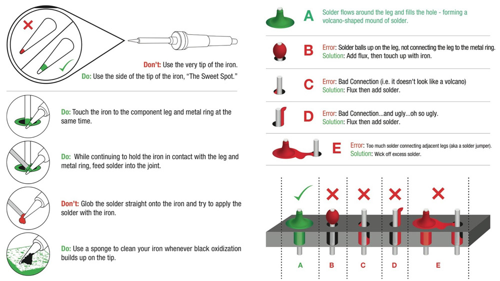 Basic tips on soldering. Image Source: [Sparkfun](https://learn.sparkfun.com/tutorials/how-to-solder-through-hole-soldering)
Part 1: Know your sensors’ characteristics
Here's an important acronym: RTFM (google it)
Main things to look out for in a datasheet:
- Minimum / Maximum operating voltage
- Minimum / Maximum operating temperature & humidity
- Logic level voltage
- Current consumption (at various states)
- If sensor is analogue, a relationship graph between sensor's output voltage and sensed input will be provided
- If sensor is digital, information on how to access it using 1-wire, I2C, or SPI interfaces will be provided
- Digital interfaces suffer from complete signal loss if wiring is too long / badly put together
- Any unique operation requirements / information
Most manufacturer datasheets will also provide detailed schematics of ideal circuit setups for operation. Here you will find out the rating of the decoupling capacitors needed.
Part 2: What sensor do I use?
Refer to Curated Links and Sensing Recipes section, with links to suppliers and other supplementary sensor information. It will be next to impossible to list down all types of sensors we can us here, as it largely depends on the scenario and specific needs. The links provide a good overview of the most typical sensors we employ in basic sensing applications interactive electronics prototyping.
Generally, sensors range from entry-level discrete components that are cheap, and not entirely robust, to industrial-grade sensors with ruggedised casing and industry-standard protocols (for example, 4-20mA current loop sensing, CANBus, RS-485). With additional supporting circuitry, it is safe to assume that the Arduino is able to work with most, of not all, of these sensors.
Part 3: Sensor Interfaces, Wiring, Wireless
Some sensors come with digital interfaces. Typically, digital sensors tend to be of higher quality, providing better precision and accuracy in its readings. That is not to say that analog sensors are inferior, but as the Arduino's ADC (analog-to-digital converter) resolution is only 10 bits (0-1023), and the Particle Photon 12-bit (0-4095), there's only so much precision microcontrollers can process in terms of analog voltage.
Analogue sensors rely on the ADC, and specifically the use of analogRead commands to convert the analog output from the sensors to a numerical input on the Arduino. Digital sensors make use of a different approach.
SPI and I2C are the two most common digital interfaces used by sensors. Both also allow daisy-chaining of multiple sensors, and generally simplifies the physical circuit that a sensor needs to connect to the Arduino.
The Arduino IDE and the Particle Photon comes with SPI and I2C code examples and libraries to allow easy connection to such sensors. Think of this as having freeways pre-constructed for you to access the sensors. You will however need to write specific code for each sensor in order to communicate with it. Fortunately, the open source community has contributed free code for you to easily integrate, say, an ADXL345 accelerometer to your Arduino code. Again, it will be impossible to list all of the libraries here for every single sensor that someone has written a library for, but you can refer to this page on the official Arduino website to get started.
A tip is to google the name of your sensor, followed by Arduino library – you'll very likely get usable results and resources to published libraries. Most of these libraries come with example sketches too, to test basic functionality.
Going Wireless: Radios
Wireless sensing might be useful for the following reasons: the sensor needs to be far away from the PC where data is logged to, or the sensing area might be difficult for connecting wires to access. Converting to a wireless sensing setup does introduce a slew of additional work. We'll discuss these during the workshop, and will use predominantly the XBee and the Nordic NRF24L01+ as a comparison.
The XBee Series 1 radio, in my opinion and experience, is the easiest way to have wireless communications working. With the right supporting hardware (the XBee USB Dongle Explorer, getting a pair of these to work is as simple as connecting the Rx/Tx pins on the Arduino to the radio.
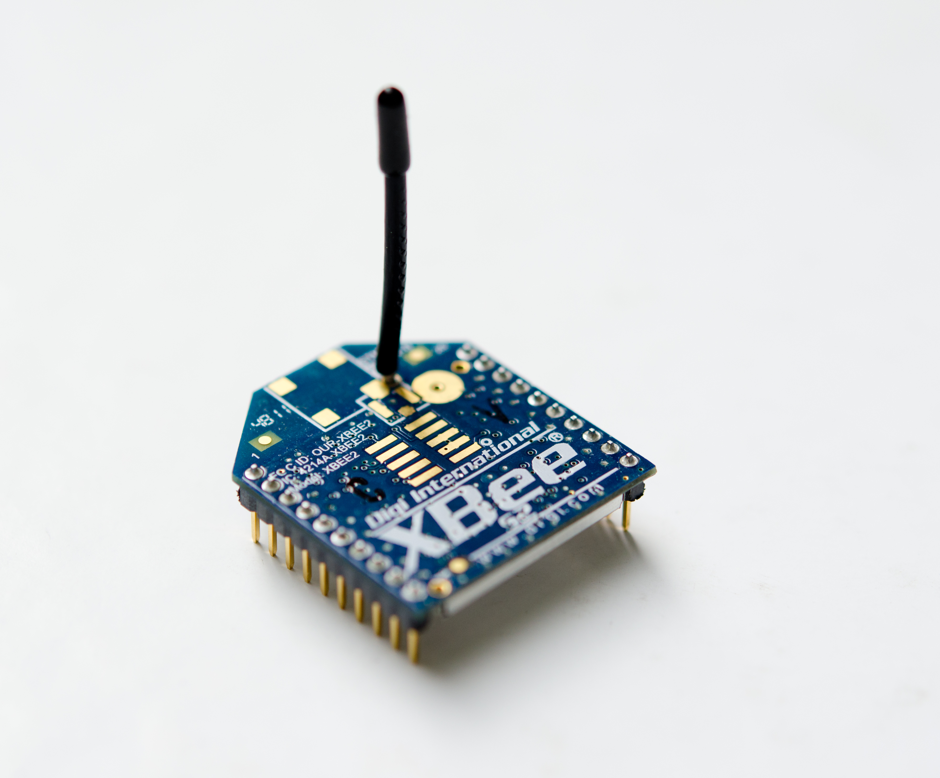 A Series 2 XBee
To differentiate between the models, there is a ‘S1’ or ‘S2’ label printed just below the large XBee logotype. XBee radios can also be re-programmed to upgrade/downgrade their system firmware. They also have very basic set of GPIOs on the radio itself so you might not even need an Arduino for very basic wireless sensing setups.
Sparkfun offers an excellent primer to the family of XBee radios: https://www.sparkfun.com/pages/xbee_guide
Most wireless setups naturally require a separate power source. Usually, this is a battery-powered source. If possible, opt for a power source that is mains-powered, such as USB cellphone chargers. The simplicity of this approach far outweighs the slight inconvenience introduced by a separate power line running to the sensor.
Other wireless alternatives:
Going Wireless: (Battery) Power?
It's very likely that your wireless sensor will need to be independently powered, sometimes ‘off the grid’. With the right circuitry, you can typically power a 5V-based Arduino using a USB cellphone charger, or use a battery power source.
Any 5V cellphone USB charger will present a good choice for powering basic 5V sensing circuits, it's all a matter of terminating the cables to appropriate terminal attachments depending on your use case. Refer to Calculating Power for more information.
There might be situations where you may have to opt for a 3.3V-based circuit. Typically this is due to the type of sensor you are connecting to the Arduino. If you rely on USB cellphone chargers as the power source, you need to select a voltage regulator that will step down 5V to 3.3V.
Similarly, if you have to use batteries, it will depend on the chemistry of the batteries you are using. 4xAA alkaline batteries will give you 6V, which should be good to power up an Arduino UNO for a decent amount of time (for a simple sensor). 4xAA NiMH (nickel metal hydride) rechargeable batterie are rated at 1.2V each (4.8V total), which may be tricky to use in 5V setups. Sealed lead-acid batteries (SLA), the same type used in car batteries, are typically rated at 12VDC and provide the longest life. You have to take care not to over-discharge them, although marine SLAs are designed for deeper discharge. Recharging and conditioning SLA batteries does require a bit more TLC than the others.
For lithium polymer (LiPo) batteries, be careful not to puncture them as they will catch fire. Not all are produced with the same quality assurance, so buy from reputable dealers when it comes to LiPo. Choosing the appropriate charger or charging circuit is a must if you decide to use LiPo batteries. Single-cell LiPos have a voltage of 3.7V, which are great for 3.3V Arduino setups. If you are using a 5V Arduino, though, you'll need either 2-cell or 3-cell LiPos (7.4v or 11.1v), or use step-up/down regulators. Multi-cell LiPos require special balancing chargers – you can source for these chargers from radio-control (RC) hobby shops. Besides the more secretive world of consumer mobile electronics, the RC industry is one of the major drivers for LiPo battery innovation (with technology that is far more accessible).
The dangers of LiPo are real:
It's not all doom and gloom, though. LiPos and their chargers these days tend to have improved consistency, and some have built-in protection against over-charging, over-discharging and temperature cutoffs. So long as you understand some basic rules of LiPo:
- No puncturing
- Don't over-deplete LiPos – they generally prefer to be kept at >80%
- Don't over-charge LiPos – most batteries will have built-in protection against this
Battery voltages
Regardless of battery chemistry, you need to consider voltage level that your battery solution provides. A 5V circuit obviously requires 5V so you need to supply an appropriate voltage step-down using voltage regulators (the Arduino UNO R3 does accept 12VDC at the barrel jack).
Voltage Regulators as decribed on Wikipedia
The long story short behind voltage regulators:
- Ideally, have a higher voltage power system than your required operating voltage, which you can then use voltage regulators to step down. Efficiency is good and you have a more stable power supply that ways
- RTFM for voltage regulators, especially notes on decoupling capacitors to achieve a stable power supply
- Linear regulators are more stable than switching ones
- If selecting linear regulators, go for low-dropout linear regulators (LDO) where possible
- Switching regulators have now become more popular due to size and lower heat emission, but note the ripple noise and efficiency ratings
- Switching regulators come in many configurations – some are step-down (bucking), while others are step-up (boost)
- Step-up (boost) regulators will never have the same efficiency as step-downs (linear or bucking), and will suffer from a diminished power output (as a result of the boost regulation)
Once again, Sparkfun has an excellent tutorial on selecting the right power source for your project.
Part 4: Signal Filtering
Signal filtering is sometimes overlooked as we prototype and test our setups and rigs. The topic itself spans years of specific research, but we can adopt some of the more common techniques in our Arduino setups.
Types of signal filtering:
| Electronic filtering | Software filtering - Microcontroller | Software filtering - PC |
|---|---|---|
| Use capacitors of suitable rating to help ‘smooth’ the voltage changes on an analog output. The high the capacitance, the more sluggish (and thus stable) the readings will be. | Write code on the Arduino to filters the incoming raw data. | Perhaps the most flexible form of signal filtering, all raw data is relayed from the sensor to the PC via the Arduino, unadulterated. The PC (and code) receiving the data then processes it. |
| Test different capacitor ratings on a breadboard to tweak the filters – not exactly convenient when everything is soldered down! | The Arduino can be reprogrammed to vary the aggressiveness of the signal filter. If you wish, connect potentiometers and code your sketch to have them alter the signal filtering strength. | Most flexible – data can be manipulated with great ease. |
| No processing calculation overhead; it's all analogue! | The microcontroller will have to work harder to filter the data on-the-fly, though for most projects it is more than capable of doing so | Not an issue for a PC to process such data. Projects that do not require a connected PC do not have this option. |
Typically, filtering is employed on both electronically and through code on the microcontroller. Filtering on the PC is seldom done, unless it's for the pre-processing of visualisations, if the Arduino is too busy dealing with more complex code, or if your PC has 3rd party software that can do a much better job of the filtering based on your project's need.
As with sensor libraries, there are Arduino signal filtering libraries that enable very easy application of such filters.
A highly recommended, simplified Arduino signal filtering library to use is the Microsmooth library, written by Asheesh Ranjan.
Generally, using this Microsmooth library, you will get good results with the Exponential Moving Average, or the less aggressive Simple Moving Average filter. The Ramer Douglas Peucker Algorithm is also worth experimenting. Filters can get costly in terms of processing power – more complex algorithms result in more noticeable ‘lag’ in the data stream.