
Software
Software setup
To begin writing code for the mote, prepare your computer as described:
- Download and install the Arduino IDE for your platform
- Go to https://github.com/esp8266/Arduino and follow the instructions to add ESP8266 board support in the Arduino IDE
- Check to make sure that you have connected a LiPo battery to the mote
- Connect the FTDI USB connection from your computer to the programmer board
- Plug in the mote to the programmer board.
- Launch the Arduino application
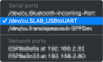
- In the Arduino application, the Serial port of your FTDI cable should be detected. Change the Port to reflect this (under
Tools > Port ...)- On the PC this shows up as a
COMxport - On the Mac you'll get a
/dev/cu.SLAB_USBtoUARTentry - Choose the appropriate port and make sure a checkmark appears next to it
- Drivers are installed automatically by Windows 10 / macOS Catalina. If for any reason the port does not appear, you might want to install the drivers manually. Also, restart your computer after installation if this still fails.
- Use a good quality USB micro cable that you know is capable of data transfer, not just USB charging. A working USB data cable is one that you know works when connecting a device that sends digital data back your laptop. Unfortunately it is very hard to tell them apart visually – low-cost micro USB charging cables do not have the Rx/Tx lines soldered to the terminals.
-
-
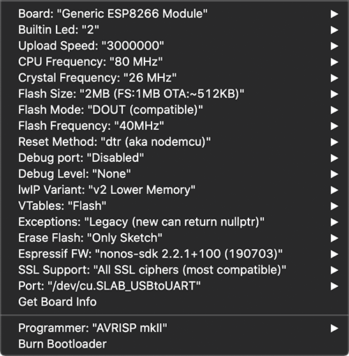
Choose Tools > Board > Generic ESP8266 Module and use the following settings:
-
To test if everything went well, upload the Blink sketch at
File > Examples > ESP8266 > Blink. Connect an LED circuit to pin IO2. You should be able to get it to blink at the interval defined in example sketch. -
One of the gripes about the ESP8266 is that uploading firmware in the Arduino IDE takes a bit more time compared to the Arduino UNO, so be patient and monitor the status pane in the Arduino IDE. The mote mini will reset itself once the upload is complete and start running your sketch
-
WARNING: Check your flash size – this is shown to you whenever you attempt to upload a sketch. Typically this is 2 megabytes (2M), you might encounter chips that have 4 or 6MB. To be absolute sure, upload the
ESP8266 > CheckFlashConfigsketch, open the Serial Monitor in Arduino, check the output and update the board settings accordingly. -
Explore the other examples in the ESP8266 Examples section!
-
You'll most likely be using Fritzing to document your breadboard circuit & schematic, so download the custom Fritzing parts below:
You may have noticed the internal flash chip can be configured to operate solely as firmware space, or used as a file system via SPIFFS. Follow this article to read more about using this feature. I personally won't recommend using the mote as a file system as the flash chip can wear out real quick – use an external SD card board connected via SPI instead. -
- On the PC this shows up as a