Mote
Introducing the mote family!
mote | məʊt |
noun a tiny piece of a substance; a speck: the tiniest mote of dust.
ORIGIN Old English mot, related to Dutch mot ‘dust, sawdust’.
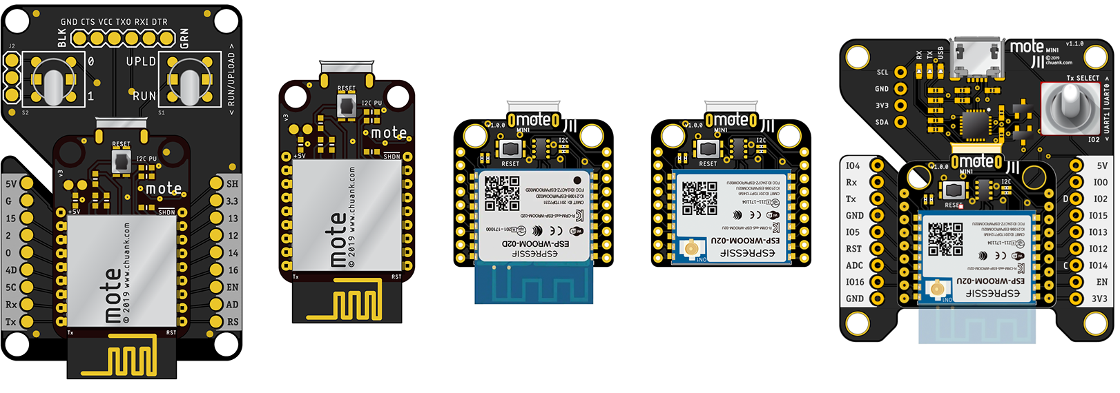
From left to right: Gen 1 mote v1.0.0 (attached to the programmer); Gen 1 mote v1.0.0; Gen 2 mote mini v1.0.0 w/PCB trace; mote mini v1.0.0 w/u.FL connector; mote mini programmer
Background
The mote is an ESP8266 split-daughterboard/programmer board solution for small-scale IoT prototyping, adapting the ESP12x and ESP-WROOM-02x form factors from Espressif. The ESP8266 is a compact, low-cost platform that can be programmed in the Arduino IDE environment. This makes it a very easy platform to learn, especially when you need to incorporate cheap WiFi connectivity to your projects. The newer ESP32 platform introduces many more enhancements to their offering including BLE and built-in sensors such as Hall Effect and capacitance touch, and more advanced sleep modes and is a forthcoming design.
In my experiments and research into the IoT prototyping space, the need for compact, battery-powered prototyping platforms is sometimes necessary. The current practice in the ‘DIY’ prototyping kit space is to adopt the common 0.1” pitch in their designs. While this pitch is handy to work with breadboards and gives plenty of room for our fingers to prod and wire temporary circuits, they are often too big for reasonably small-scale, wearable projects, which makes certain form aspects of the prototyping process difficult to achieve. If you have ever considered the possiility of realising some distant idea of say, motion-sensing earrings, you'll understand this predicament very well.
Like many other electronics tinkerers, we have encountered the same frustration evaluating power delivery and LiPo battery recharging modules. The first sacrifice is often size – by the time you put together a power regulator, charging circuitry and the microcontroller itself, you have in your hands an unwieldy hodge-podge of soldered daughterboards that you might find too big for your miniaturisation efforts. For example, Adafruit makes the fantastic Huzzah feather boards which incorporate a bucking LiPo charging circuitry, but chose to keep their designs single-sided and hence increase the overall footprint of their board. It's great to demonstrate a functional prototypes, but not so good for testing how it might all fit together (and more crucially, how a more compact prototype enables better opportunities to test actual interactions).
The mote family of boards is my attempt to address these issues. The key factors here are size and price – the Espressif modules are widely available and the small footprint is very hard to beat for its price.
If you've had prior experience with the Arduino and Particle microcontroller family, here are some key comparisons:
Differences vs the Arduino
- It's much smaller than the UNO, and still smaller than the pro mini
- It has WiFi
- It runs faster
- It runs warmer (and consumes more power)
- It uses 2mm pitch header pins instead of 0.1” (2.54mm)
- It has LiPo charging and voltage regulation built-in
- It requires a LiPo battery connected to it to work
Differences vs the Particle Photon
Adding on to the points from the Arduino list:
- It's smaller than the Photon
- The Photon has 128Kb user code space, the ESP8266 SoC supports a variable size, from 512Kb - 16Mb depending on the flash chip (typically it's 2 or 4Mb).
- The Photon runs at 120MHz vs the ESP8266's 80MHz
- The Photon uses the particle.io cloud to provide internet connectivity services. The mote mini uses MQTT as the most ideal protocol to achieve similar results
- It's easier to run tiny web servers and other TCP/IP or UDP services on the ESP8266. With the Photon, you have to use Particle's ecosystem (refer to the IoTa section – a node I wrote for node-RED is available to easily connect more data sources to your Particle devices).
The mote mini Boards
As I am running a course that will utilise the mote mini design, older content referencing the first-generation motes have been taken out. There is also the expectation that students should know the basics of physical computing and have had experience with the Arduino – the mote content published here will not cover the very basics of electronics. Don't be afraid to ask questions on Canvas if you are very new to this.There are two parts to this…
Generally, the mote ecosystem comprises of three separate boards – the mote itself, the programmer board, and a prototyping board. This allows the mote's size to be kept minimal (along with cost, since you only need one programmer for multiple motes). Cost-wise, this begins to work in your favour the more motes you prototype with, as you only need to have one programmer board.
mote mini + mote mini programmer
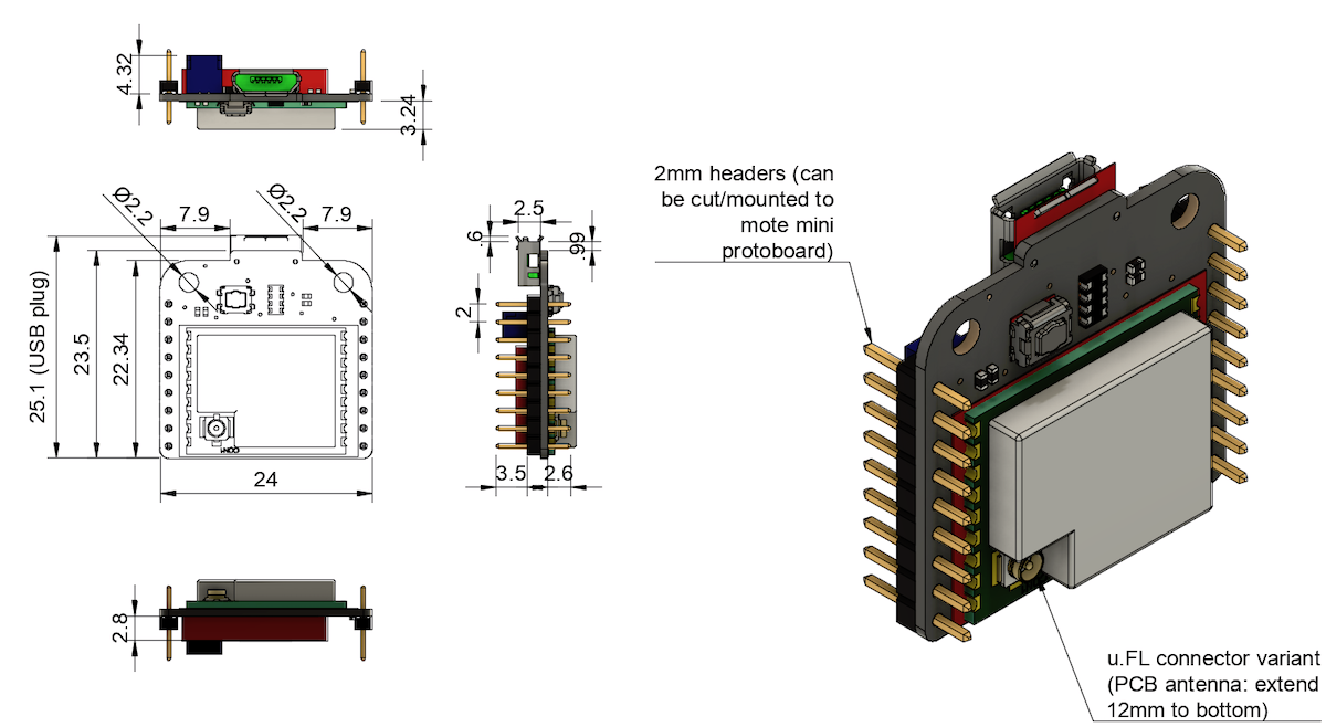
This updated design utilises the slightly smaller ESP-WROOM-02/U module. A 2mm pitch is adopted to keep things compact. Through the use of smaller SMD components, the size of this board comes up to about 25mm2. The mote mini also uses 0.8mm thick PCBs, half that of the mote.
Power is provided via a JST-SH 1mm connector. Please note that this is different from the Gen 1 mote which uses a JST-PH 2mm connector. This also means the maximum current draw should be kept to 1A.
I2C 3.3K pullup resistors come populated on the board – this provides the cleanest pullups on a single I2C device. They are also located at a spot that's relatively easy to rework if you need to change the resistor values.
The programmer board gets a major upgrade compared to the Gen 1 mote – it now utilises a SiLabs CP2104 UART chip on the board itself. This means you just need a micro USB cable to connect to your computer – no more horrors with the dreaded FTDI cable & drivers.
The programmer now also has an automated programming/reset function similar to the Arduino. This means no more flicking of switches and/or buttons to get your code sketches uploaded to the mote mini, just click Upload in the Arduino IDE (provided you set up the configuration properly).
One big switch remains on the programmer board to toggle between UART0/1. Normally you want this switch pointing ‘north’; i.e. upwards to use UART0.
ERROR ALERT! The v1.0.0 boards have errors resulting in the Tx/Rx LEDs on the programmer staying on instead of flashing only when there is seral port activity. In my defense, it still works without issue :) The more glaring mistake is the reset button on the mote mini which was not routed to the reset pin; these v1.0.0 boards will have a little patch wire fixing this mistake. Yes, I lived to tell this tale, and have learnt my lesson well. :)Pinout / Switches
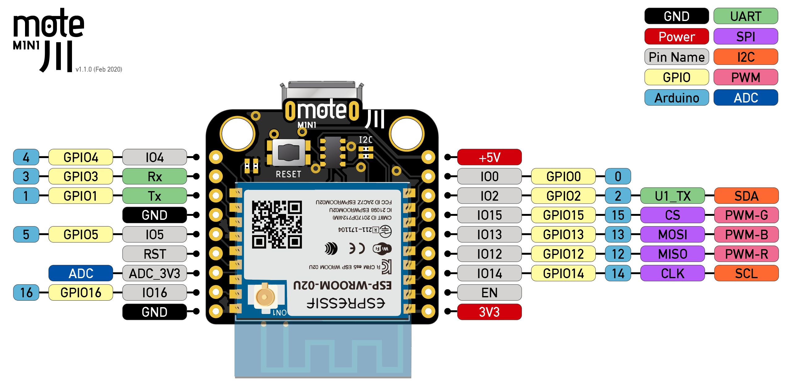
This section describes the pins broken out, including specific modifications to pins that have differed from the ESP8266.
I have also produced Fritzing library parts for the mote mini family of programmer and board. Note that this library does not have the actual PCB footprint, just the breadboard and schematic diagrams. Click on the link below to download it:
Two variants of the Espressif ESP8266 SoC can be used – one with an on-board PCB trace antenna (ESP-WROOM-02) and the other being a u.FL antenna connector (ESP-WROOM-02U) that you snap a 2.4GHz antenna on. Note that the u.FL connector is not designed for repeated plugging/unplugging. The PCB antenna is easy to use but extends the size of the board, while the u.FL antenna connector can be fragile but allows the antenna to be adhered to your enclosure to find an optimal signal reception.
The Espressif modules are soldered ‘upside-down’ to allow the antenna side to face away from everything else on the PCB. If you are using the PCB trace antenna (ESP-WROOM-02), note the increase in vertical size (shown as a ghosted overlay above).
Power notes
- The +5V pin is typically used when the mote mini is plugged in to the programmer board. You could also connect a (max 6V) solar panel to this pin.
- The 3V3 pin is the voltage output from the onboard switching voltage regulator. You can use this pin to power sensors and other similar peripherals.
Maximal output current from 3V3 pin can be calculated using the formula Imax = (1000mA - total current for ESP8266 chip).
The ESP8266's average operating current is 80mA, while the maximum current draw from a GPIO pin is 12mA. Depending in your application you can then calculate the available output current.
- The ESP8266 chip runs warm, so don't be alarmed if the metal case feels warm to the touch. However, it should never be hot enough that you can't place your finger on it indefinitely.
- You MUST plug in a LiPo battery in v1.1.0 and below of the mote mini. A LiPo battery is needed to provide power to the mote mini at all times during use, even when plugged into the programmer.
- The mote mini is NOT designed to directly power motors – the use of an I2C dedicated motor controller is suggested.
If you intend to use the mote mini to control servos, high-powered LEDs and the like, be sure they have a separate power supply and tie all grounds together. Hobby servos, for example, are rated at 5V and draw upwards of 1000mA at full load, so be aware that the mote mini is never designed to drive them directly.
ADC_3V3
The ADC pin is connected to a 0.1% tolerance voltage divider to safely step a 3.3V analogue voltage input down to the 0-1V range that the ADC pin reads. This means you no longer need to build a voltage divider externally – if your analogue sensor outputs 0-3.3V, you are good to go!
WARNING: Do not connect anything more than 3.3V to the ADC pin.I2C
The I2C bus is pulled up on the mote mini using 3.3k resistors. On the programmer board, a 0.1” through-hole header is available to allow easy access to the SDA/SCL, power and ground pins.
ERROR ALERT! *sheepish grin*The v1.0.0 programmer boards mislabelled the I2C pins. Essentially the SDA and SCL labels are reversed.
Refer to the image BELOW LEFT which shows the correct pin labels.
The v1.1.0 programmer boards (BELOW RIGHT yet-to-be-manufactured) now adopt Sparkfun's QWIIC arrangement.
Note: the Fritzing parts includes both variants, so choose the variants from the Part Inspector carefully! Sorry.
Differences between the v1.0.0 and vv1.1.0 boards
Declaring the SDA/SCL pins in the Arduino IDE
The I2C bus on the ESP8266 is software-driven, which means we can assign any pin as SDA/SCL. The generic ESP8266 board setting in the Arduino IDE uses a different set of SDA/SCL pins compared to the mote mini.
This means that if you intend to use I2C with your mote mini, you need to instruct the compiler to explicitly use
IO2andIO14as SDA and SCL respectively. Call theWire.begin(SDA, SCL)command just before you initialise your I2C device, like so:
1
2
3
4
5
void setup() { Wire.begin(2, 14); // set SDA/SCL I2C pins i2cDevice.begin(); // for example, to instantiate the I2C sensor you are using ... }Dimensions
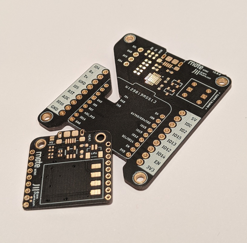
Add-on: Prototyping board
The programmer board provides easy access to the pins via 0.1” header sockets. This makes initial prototyping easy to set up. Once you hve a working circuit, you can consider the mote mini protoboard as a more permanent wiring layout for your project:
mote mini and protoboard. Note how the board fits under the mote mini, with a cutout to allow access to the battery connector. Solder 2mm header sockets to the protoboard to allow quick insertion. Watch out for the vertical clearance of the components under the mote mini, though!
The protoboard has standard 0.1” plated-through-holes (PTH) for you to populate components. Obviously if you are using large sensors this won't give you enough real estate, but nonetheless this offers a good ‘staging board’ area to break out connectors to larger peripherals.
Caveats
Please bear in mind that I am not an engineer by training; the development and testing of mote was borne from a need to meet my own research needs and has turned out to be a rather fun learning adventure for myself. The mote family is essentially an assembly of various parts, tested to work well together, and designed for an intended application – smaller-scale prototyping with the IoT. Comments and suggestions are welcome but as always: YMMV. Don't use this in mission critical, life-or-death projects.
The mote mini is designed with size and portability in mind. As such, certain sacrifices were made – more fragile construction, noisier power line, and a strict 3.3V operating environment. It's not as forgiving as say an Arduino.
Want to test this board in your project? Ping me on Github/LinkedIn and I'll see if there are spare boards around!
Copyright 2019 Chuan KhooPlease note that the mote and mote mini designs, including the programmer boards, are the intellectual property of Chuan Khoo and is NOT licensed under any Creative Commons license that the rest of this online resource is attributed to.