
Setup/First Steps
Familiarising yourself with the mote hardware
If you are new to physical computing, it is recommended that you use the Arduino IDE as the starting point for writing code for the mote. These articles will use the Arduino IDE as the coding platform.
Here's a quick introduction video to ease you into the world of microcontrollers:
The mote mini has two components:
- the Programmer Board (left)
- the actual microcontroller (right)
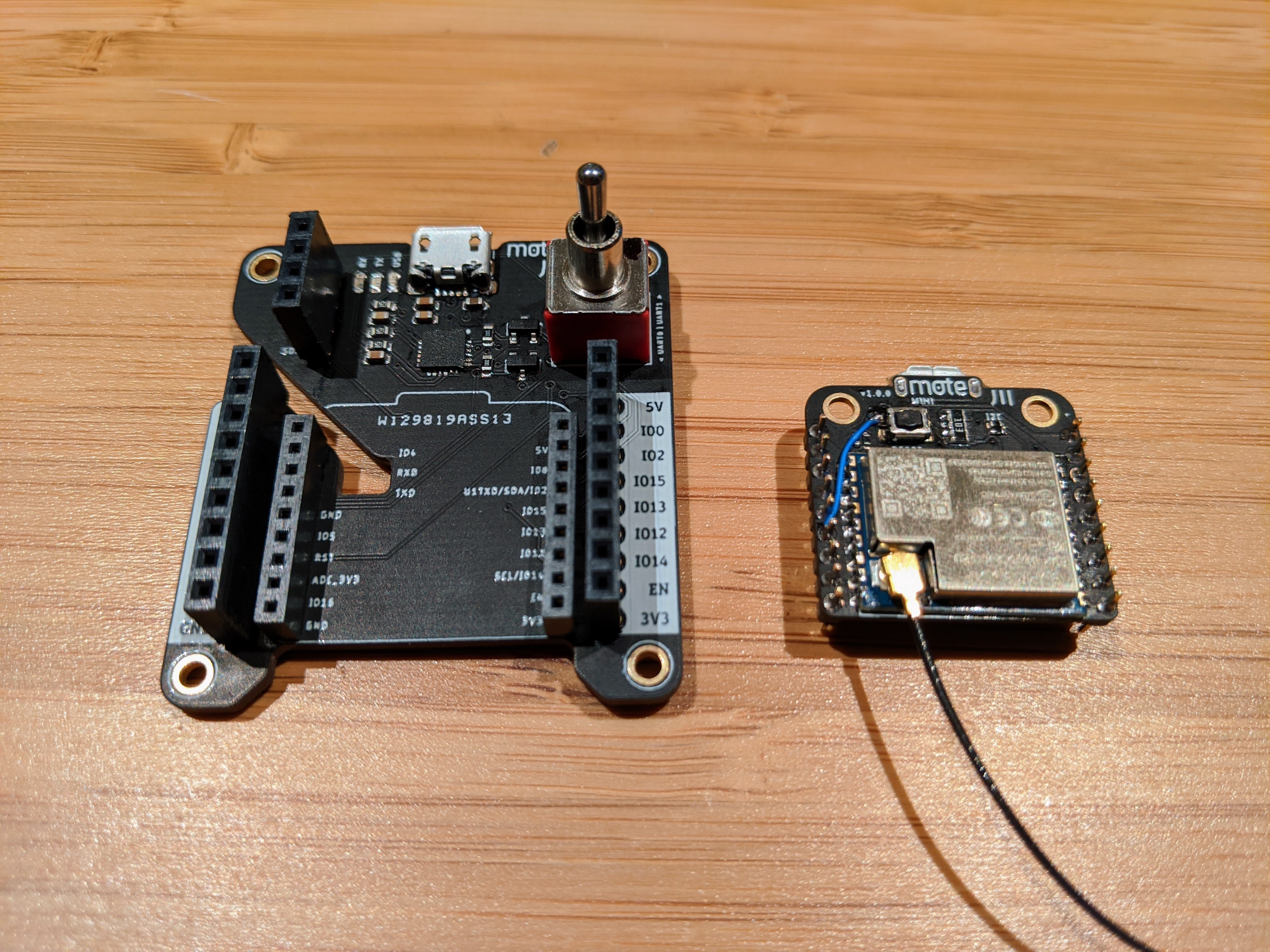 Left: programmer board; Right: mote mini, u.FL external antenna used
The larger programmer board has a micro USB plug that you connect to your computer. When connected the green power LED will light up.
One red switch
The large red toggle switch, labelled “UART0/UART1”, switches between UART0 and UART1 serial communications to the computer. Most of the time, this is kept at position 0, i.e the switch flicked upwards in the direction of the usb connector. UART0/UART1 are the two discrete serial interfaces that the ESP8266 has, and comes in handy for advanced debugging where you want debug/trace messages coming out a different serial port.
What's that micro USB jack on the mote for?
This is just a recharging point – plug in a micro usb cable connected to a USB port or power bank to charge the connected LiPo battery. It will automatically stop charging when full. This USB connector does NOT transmit data.
Connect a charged LiPo battery to the underside connector of the mote mini. You should do this before attaching the mote to the programmer as it's easier that way. This connector is keyed, so there is only one way to insert it.
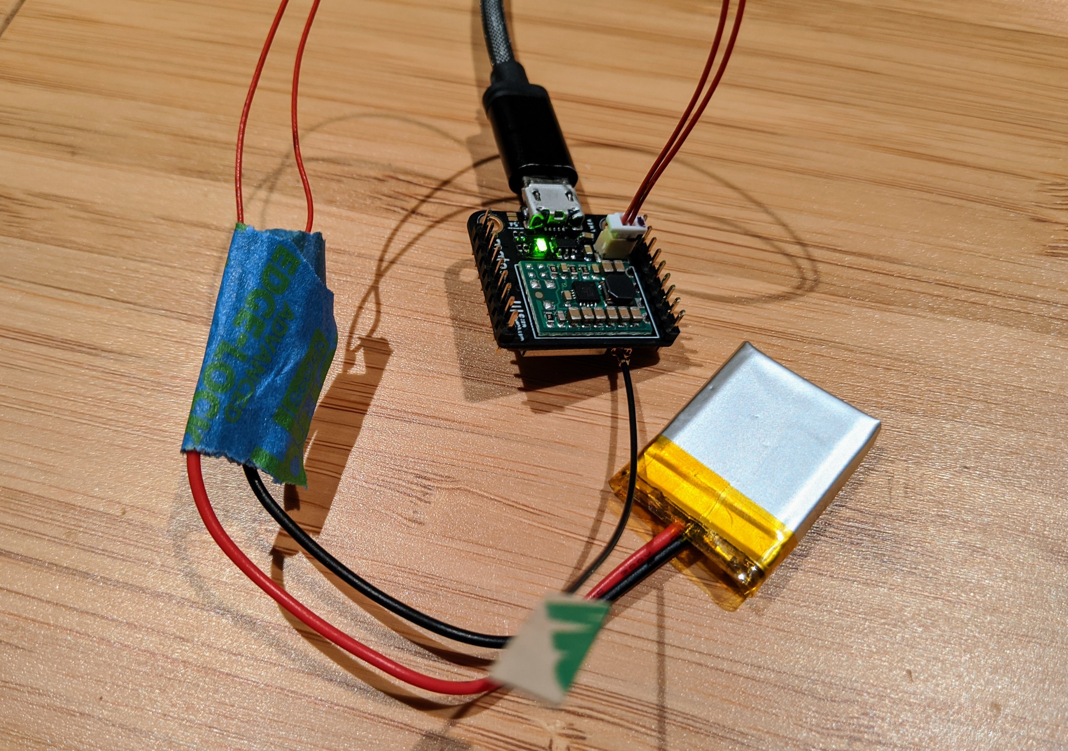 LiPo battery fully charged as indicated by green LED
- A red LED on the mote means charging is in progress, or that a LiPo battery is not connected.
- A green LED means the battery has been fully recharged.
When to attach the mote mini to the Programmer Board
Typically, you'll connect the mote to the programmer to upload firmware, or prototype with breadboards using the 0.1” header sockets broken out on each side of the programmer board.
When initially designing your prototype, you should keep the mote mini attached to the programmer as this gives you much easier access to the various labelled pins on the 0.1” sockets which are much more breadboard-friendly. Once you have confirmed proper operation of your prototype are are ready to build the final miniaturised version of your project, you can request for a prototyping board the same size as the mote mini that you can stack the mote mini on top of.
Carefully insert the mote mini into the programmer board, as shown in the below image. If done correctly, there shouldn't be any gold header pins exposed from underneath the mote:
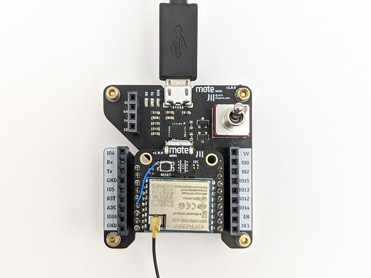
You are now ready to setup the software environment and upload your first “Hello, World” sketch to the mote!