Physically, quite possibly the simplest circuit of all – it's a blank slate full of possibility!
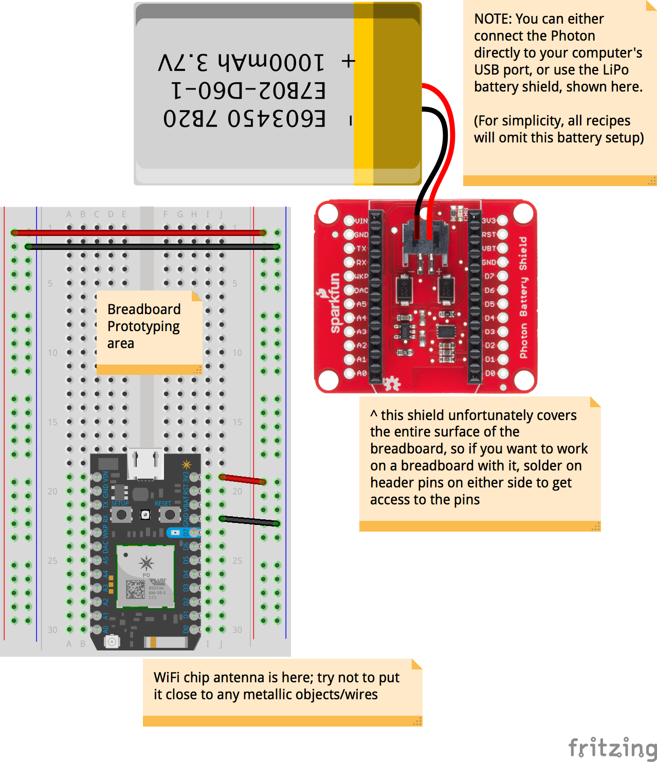
NOTE: The LiPo Battery and red Photon Battery Shield are optional components should you decide to have a wireless, rechargeable solution especially for remote data recording via a mobile phone's hotspot. Ignore those parts if you are simply trying to understand the Photon basic circuit foundation and code.
The magic in this case happens in the code. There's not much in the way of the breadboard wiring.
This blackbox does not do anything by itself, but forms the basis of many other recipes in this studio. What you have here is a Photon configured, in code, to ‘publish’ data it's listening to, back to the Particle server which means we can then tap into this feed via IoTa/node-RED.
Copy and paste the code below into your Particle Build IDE. There are no libraries to import in this case.
By default, this code does the following:
D0 and D1 are configured as INPUTs, allowing you to connect simple digital sensors/switches to it
publishes the readings from pins D0, D1, A0 and A1 to the Particle cloud (for IoTa/node-RED to subsequently connect to)
As the physical circuit is not connected to any sensors, you'll get a bunch of randomly-fluctuating numbers at this stage. This is to be expected.
In the Sensing Recipes section, you'll notice how each basic sensor recipe is just a simple variation of this basic A/D Blackbox. The exception comes in the form of specialised digital-protocol (I2C) sensors.
// how long between each log update? feel free to change this value,
// but this must not be anything less than 1000 milliseconds!
#define INTERVAL_BETWEEN_LOGS 5000// initialise the timer
Timer dataTimer(INTERVAL_BETWEEN_LOGS, doDataUpdate);
// code in this setup function runs just once, when Photon is powered up or reset
voidsetup() {
Serial.begin(9600); // Open a connection via the Serial port / USB cable – useful for debugging
delay(5000); // Common practice to allow board to 'settle' after connecting online
dataTimer.start();
pinMode(D0, INPUT_PULLDOWN); // tell the Photon we're using D0 as an INPUT (pulldown resistor enabled)
pinMode(D1, INPUT_PULLDOWN); // tell the Photon we're using D1 as an INPUT (pulldown resistor enabled)
// if you're adding more digital pins as INPUT, add lines similar to the above accordingly.
// note: analogue pins do not need to be initialised as they are INPUTs by default
}
// code in this loop function runs forever, until you cut power!
// for the A/D blackbox, there is nothing to do in here because data updates are handled by our timer
voidloop() {
}
// doDataUpdate runs every interval set in INTERVAL_BETWEEN_LOGS
voiddoDataUpdate() {
// IMPORTANT: to prevent server overload, the Particle cloud can only accept
// update rates of once per second, with the option to 'burst' 4 updates in a
// second (but then you'll get blocked for the next 4 seconds). 'Ration' your
// INTERVAL_BETWEEN_LOGS and the number of readings you are publishing; in our
// default example, we are frugally using just 1 publish, by concatenating
// all the data we want into a single publish statement
// first we save what we want to read into temporary variables first.
// feel free to add/remove these lines as you see fit in your application:
bool D0State = digitalRead(D0); // read a digital true/false state from D0
bool D1State = digitalRead(D1); // read a digital true/false state from D1
int A0State = analogRead(A0); // read an analogue range (0-4095) from A0
int A1State = analogRead(A1); // read an analogue range (0-4095) from A0
// now we form the concatenated string to put them all together. This String
// must NOT exceed 255 characters!
String output ="D0:"+ String(D0State) +",D1:"+ String(D1State) +",A0:"+ String(A0State) +",A1:"+ String(A1State);
// prints this out the Serial port (coolterm) for us HUMANS to verify and
// debug; comment the next line if you don't want to see it in Coolterm
Serial.println(output);
// finally, send it out (and have sensored.mdit.space receive it):
Particle.publish("sensorData", output);
}