LEDs! Bright, colourful fun things that are often seen as tacky, or simple – but that just means you haven't experimented with the nature of light itself!
In this recipe we use basic 12V RGB LED strips, which are also known as LED Tape in some circles.
A crucial differentiator between these RGB strips and 'addressable' versions (the NeoPixels, WS2812B etc) is that you can change the colour output of a 12V RGB strip ALL AT ONCE, but not individually. If you want individually addressable LEDs, NeoPixels are the answer ([see other recipe for Neopixels](../02-led-ws2812b)).
Knowing this limitation, 12V RGB LED strips are nonetheless great options for having controllable lighting in your work. Working with light often requires you to consider the absence of light, i.e. the shadow, and this, as with any craft, is as much an art and creative endeavour as it is a technical one.
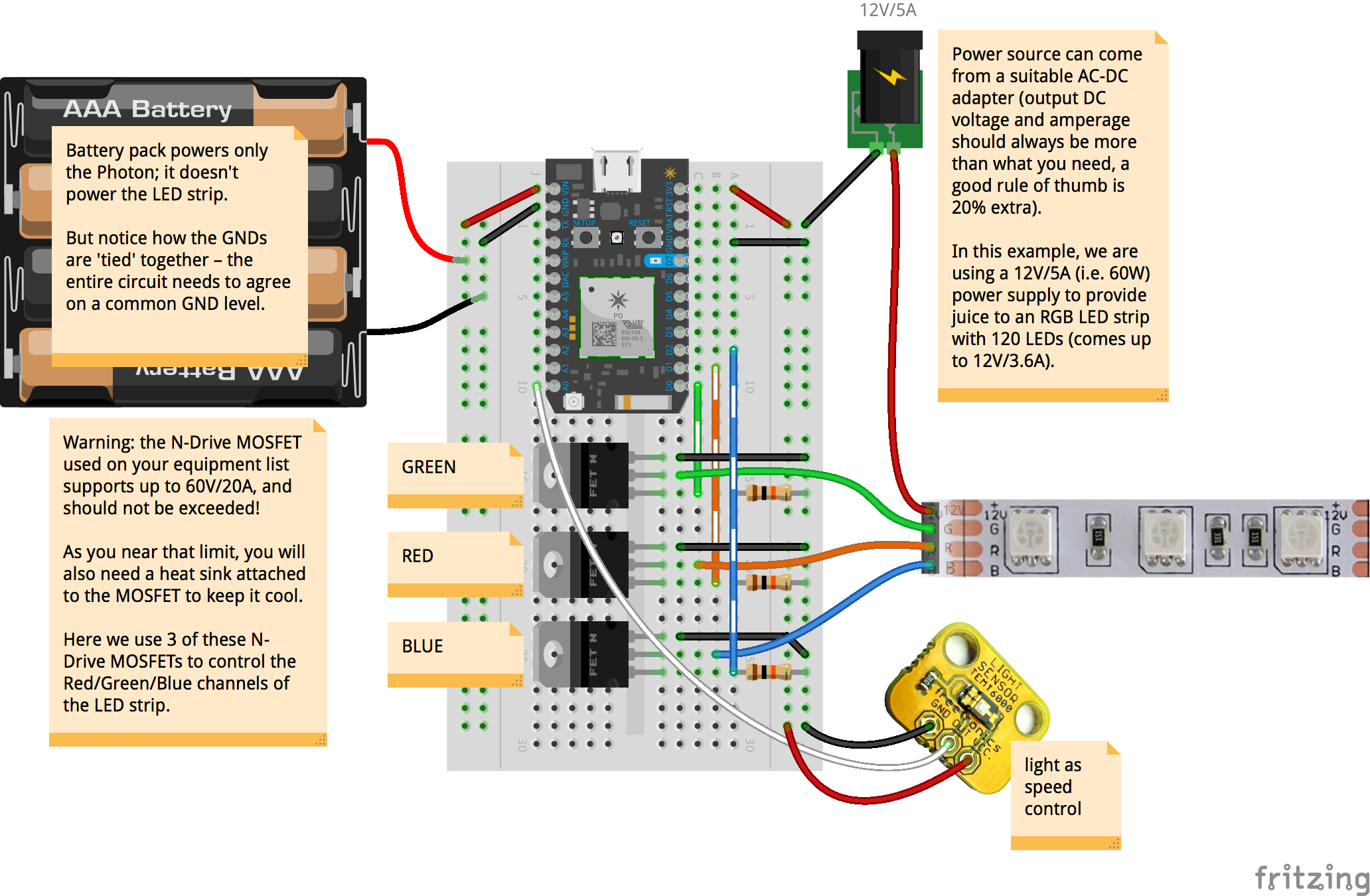
You will definitely need a wall-wart transformer that can supply sufficient power to your LED strip.
A typical 12V RGB LED will draw up to 20mA (0.02A). Therefore, a typical 60-LED-per-meter strip will draw a maximum of 1.2A. They do add up, so make sure you choose the right 12V power supply accordingly!
Video on how to cut 12V LED strips
You can swap out the light sensor with any other analog sensor in your kit, so long as you modify the code to suitably adjust the scaling of the sensor readings in relation to the desired output.
The code is getting the ambient light sensor to drive the Red, Green and Blue channels simultaneously, which means the LED strip will be generating a ‘white’ light by combining Red/Green/Blue colours.
To keep kit costs low your equipment list includes only one N-Drive MOSFET. If you connect this to the Red channel you'll get a simple Red LED strip that responds in Red intensity to the ambient light sensed. Order extra N-Drives on your own, if you find that your experimentation is leading you to use RGB LED strips.
// code in this setup function runs just once, when Photon is powered up or reset
voidsetup() {
Serial.begin(9600); // Open a connection via the Serial port – useful for debugging
delay(5000); // Common practice to allow board to 'settle' after connecting online
pinMode(D0, OUTPUT); // goes to N-Drive #1, 'red' channel
pinMode(D1, OUTPUT); // goes to N-Drive #2, 'green' channel
pinMode(D2, OUTPUT); // goes to N-Drive #1, 'blue' channel
}
// code in this loop function runs forever, until you cut power!
// for the A/D blackbox, there is nothing much in here except to update the Blynk App
voidloop() {
updateLED();
}
voidupdateLED() {
int sensorReading = analogRead(A0);
int scaled = map(sensorReading, 0, 4095, 0, 255); // tweak these numbers accordingly!
scaled = constrain(scaled, 0, 255); // make sure scaled ranged is within 0-255
Serial.println(scaled);
// write the scaled output to the NDrives
analogWrite(D0, scaled); // red
analogWrite(D1, scaled); // green
analogWrite(D2, scaled); // blue
}